


-
 I have discovered that my post above is not correct. I have not found a way (using a meter) to verify if a silicon controlled rectifier or transistor is "on" or not.
When accomplishing a diode check with the meter, I get the same results with a live circuit as I would with aircraft power off. Meaning..... you can't rely on on this type of check to verify if a active ground is being supplied through the card or circuit.
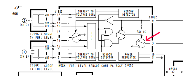
I'm guessing the current carrying capability of these ground signal components is rather small. They are usually used to activate relays which control other user systems downstream. [In the image above, a ground signal is used to control a relay that allows the valves to open for fueling operations. If fuel is present in the surge tank(s), the card removes the ground which causes the fueling relay to relax and kill power to the valves. This keeps fuel from spilling on to the ground.] A full explanation of this circuit can be found here .
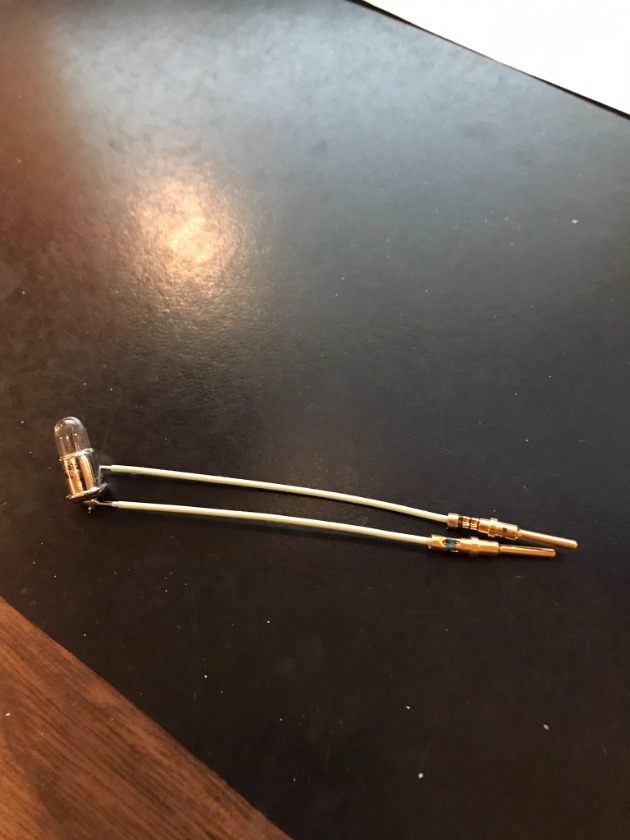
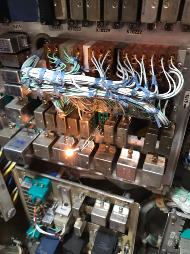
I used a small peanut bulb (327 Bulb) as a signal light to verify if this particular ground signal was present or not. This is about a .1 amp draw on the system. (I'm guessing a typical relay coil is about .75 amp draw.) Using one of these small bulbs allows you to check the circuit without frying the card.
Post is under moderationStream item published successfully. Item will now be visible on your stream.
Rotate Aero Users
Random acts of kindness are contagious!!
Don't have an account?
Register now to join the community!
©
2026
Rotate.Aero