Pinned Items
Recent Activities
-
I think you're getting into component level repairs.
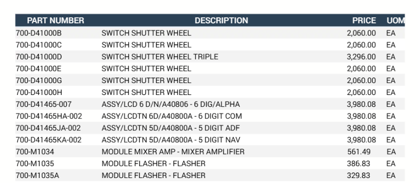
That part comes up as a Gables "Switch Shutter Wheel".
Gables makes VHF Communication Control Heads and Audio Selector Panels.
Repairs of these components is done in qualified and certified repair shops.
Line maintenance replaces these units when needed, but we do not open the panels up for internal repair.
Post is under moderationStream item published successfully. Item will now be visible on your stream. -
I have no clue as to the type of system installed on your aircraft.
This would be a add-on from the the original delivery configuration, so I would think you would find information in a Supplemental Maintenance Manual.Post is under moderationStream item published successfully. Item will now be visible on your stream. -
We recently had a pitot probe that was not pulling enough current in the low power mode to satisfy the current flow relay. The associated overhead warning light and EICAS message were on. The probe "was" getting hot
This problem was noted by the crew right after the first engine was started. The engine speed cards are what turns on the probes in a low heat mode.
When the aircraft was placed in the "air" (or high power) mode, the failure indication was gone. It also was gone when trying the probe heat test switch.
After wasting about an hour chasing relays..... we hung a new probe on the connector and tried low power..... it worked normal.
After digging into the print, it was noted that the test switch puts the probe in a high heat mode.Post is under moderationStream item published successfully. Item will now be visible on your stream. -
The main purpose of the flight deck access system is preventing unauthorized entry into the cockpit.
The flight crews can lock/unlock the door with a switch (usually on the overhead panel).
There is a panel on the outside of the door that a numeric pass code that can be punched in to allow the door to unlock.Post is under moderationStream item published successfully. Item will now be visible on your stream. -
The site has been spotty at best over the last few days.
Hopefully, the issues have been corrected.Post is under moderationStream item published successfully. Item will now be visible on your stream. -
A schematic print would be nice.
You're dealing with older 737's if I remember correctly.
The interphone system on this aircraft would be considered analog.Post is under moderationStream item published successfully. Item will now be visible on your stream. -
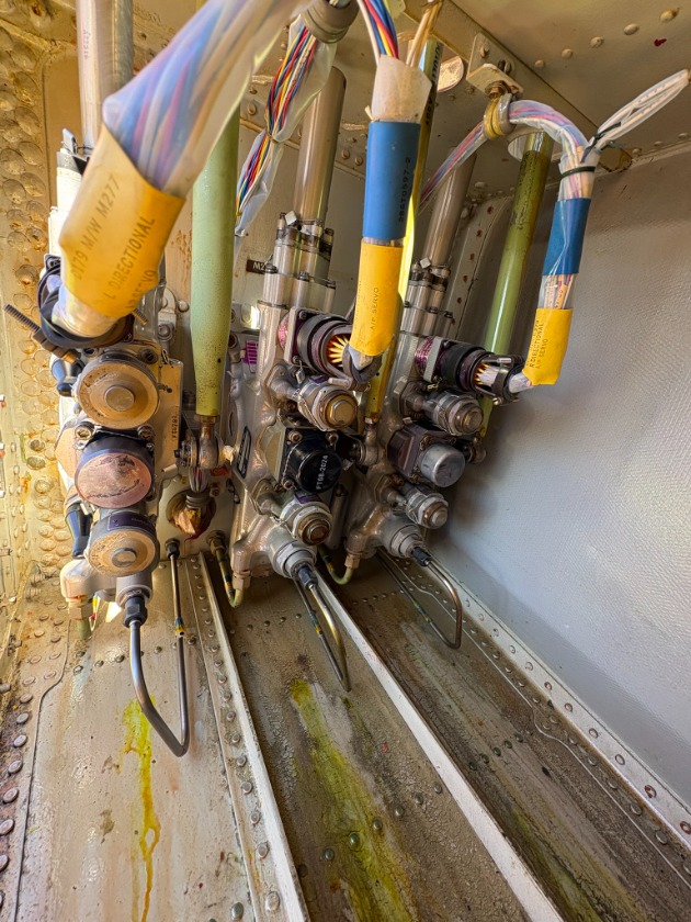
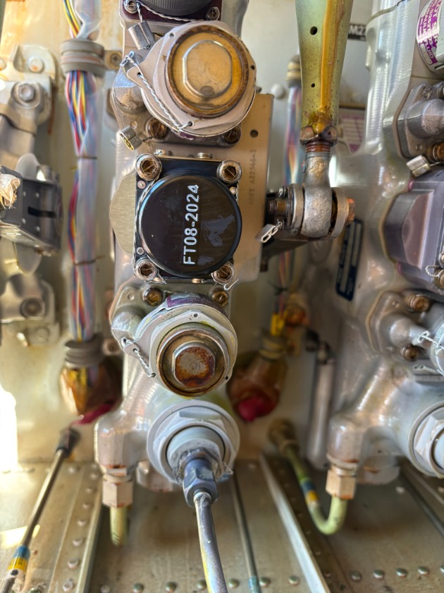
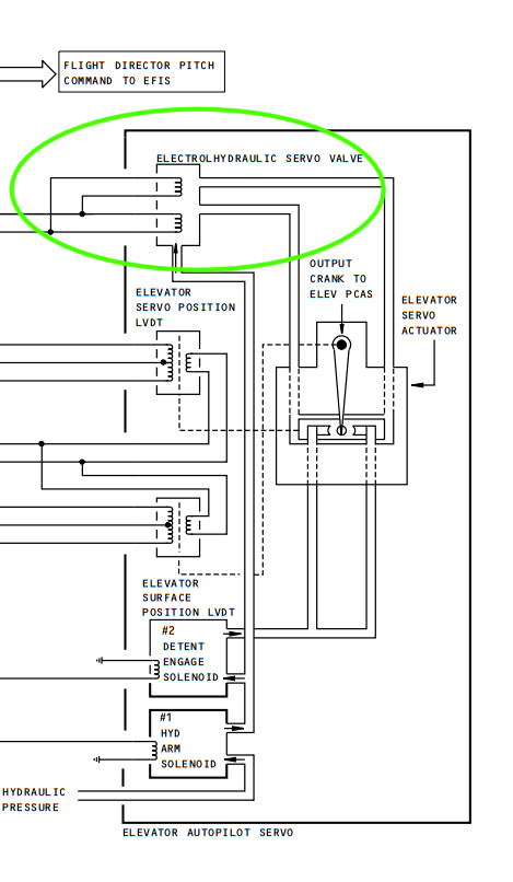
On the 767, all auto-pilot actuators are the same part. There are nine total. 3 each for pitch, roll, and yaw.
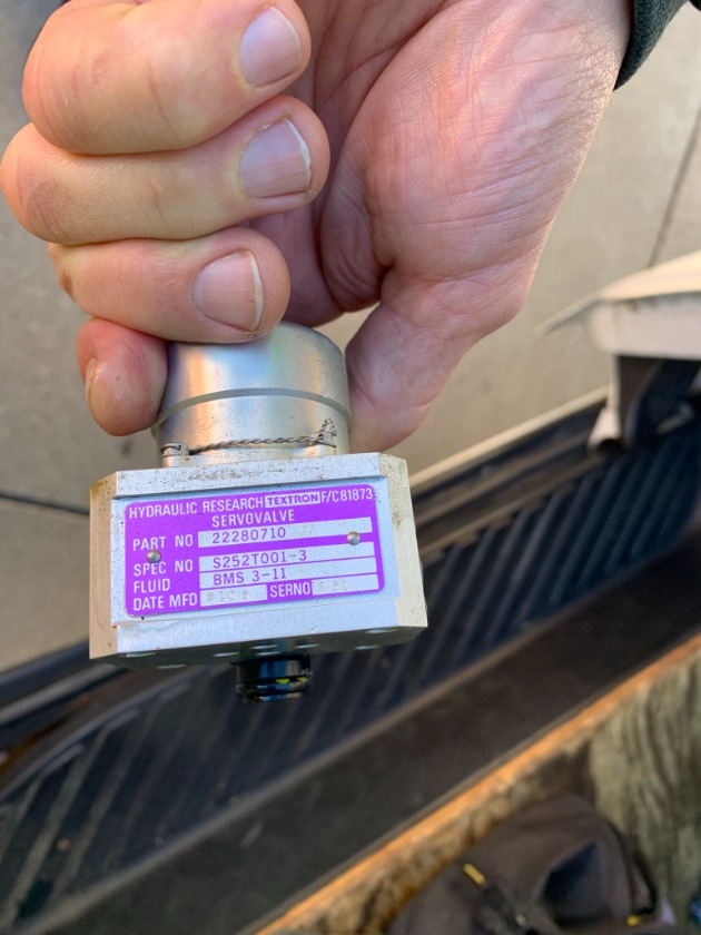
On each servo there are line replaceable electrohydraulic servo valves and shutoff valves.
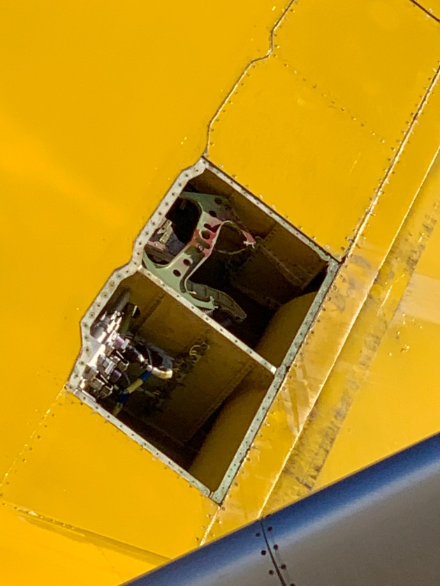
We recently had an aircraft with a center auto-pilot that was not engaging. The MCDP checks showed a failed command circuit for the rudder (or directional) servo. The rudder servos are inside the vertical stabilizer.
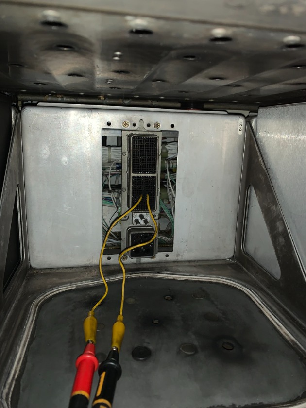
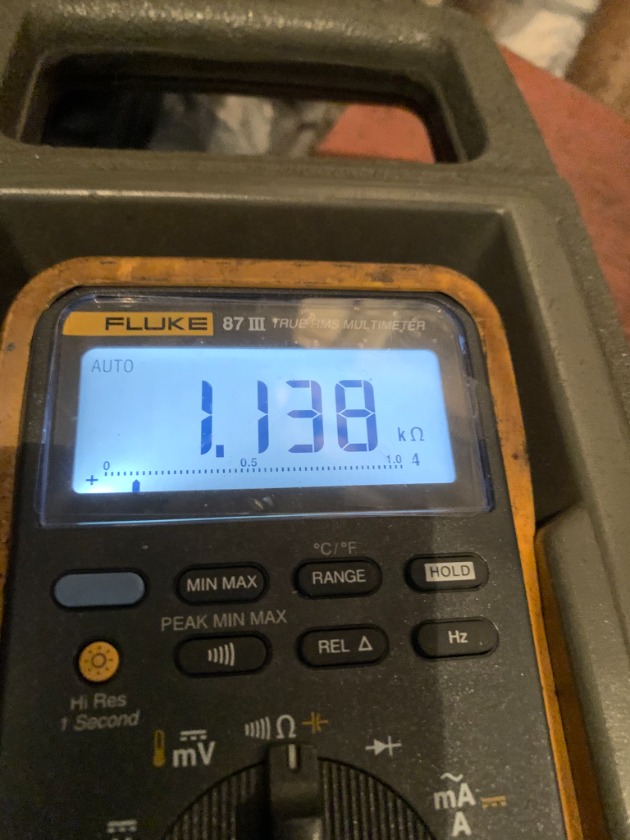
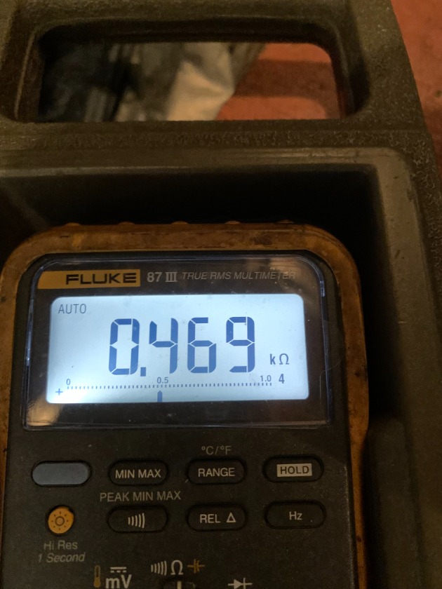
When the valve was checked from the Center FCC, a reading of approx 1100Ω was seen.
You would think "I've got continuity so the valve is good", but that would be wrong.
There are actually two coils wired in parallel. 1100Ω is the resistance of "one" of the coils.
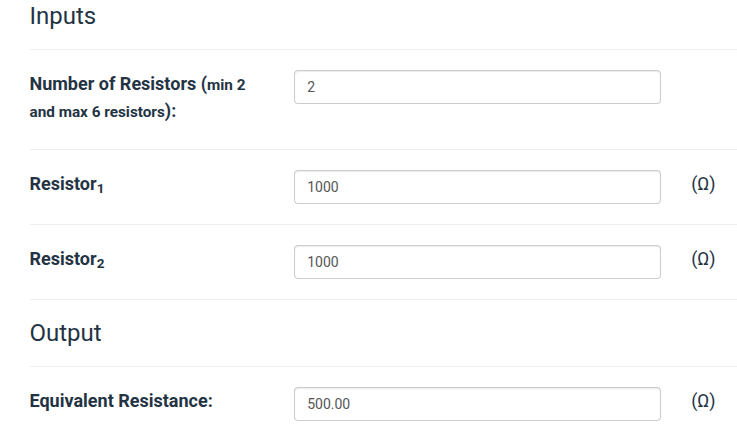
When two coils of basically the same value of 1000Ω are wired in parallel, total resistance is about half the value of one.
When the replacement valve was plugged in, the value read at the FCC rack dropped to about 500Ω.
It should be noted.... the servo (or shut-off) valves plug into the case of the actuator. If we had the same resistance reading with the replacement valve, we would most likely have a open wire internally "in" the actuator. That would suck as now the whole unit would require replacement.
Post is under moderationStream item published successfully. Item will now be visible on your stream. -
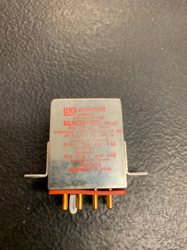
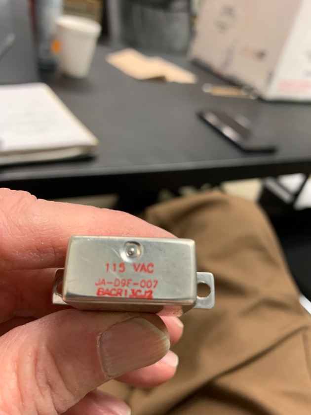
Leach relay P/N BACR13CJ2 causing a cycling "FLAP/SLAT ELEC" warning on the lower EICAS display.
This is different from the posts above because this one has a 115 VAC coil. All previous intermittent relays were direct current.
This particular one was failed for about 90 seconds and energized around 10. (I wouldn't have caught it if I wasn't looking at the EICAS screens for another reason.)
When failed the message was in view.
I pulled the relay and checked for power (X1) and ground (X2). These inputs never dropped off. I then jumped the 115VAC and a separate hard ground to the removed relay. It dropped off within 10-15 seconds after power was applied.
A new relay fixed the problem.
In the schematic below, the EICAS computers do not want to see a ground on "F3" of the "D" plug. If a ground is present..... the warning will display.
K730 has 115 VAC available all the time. It's looking for a ground to energize. That ground comes from the Flap Slat Electronics Unit on pin "K13" of the "B' plug. If the FSEU is operational, it will provide that ground and there will be no warning present.
Post is under moderationStream item published successfully. Item will now be visible on your stream. -
Old, but it still gives some good information.
Same system on 767.
Post is under moderationStream item published successfully. Item will now be visible on your stream. -
I'll reach out to the poster to see if he can help you out.Post is under moderationStream item published successfully. Item will now be visible on your stream.
There are no activities here yet


