


-
 High Frequency communication is mainly used over open oceans, out of VHF (approx... 200 miles) range. HF frequencies run from 2.800MHz to 23.999MHz.
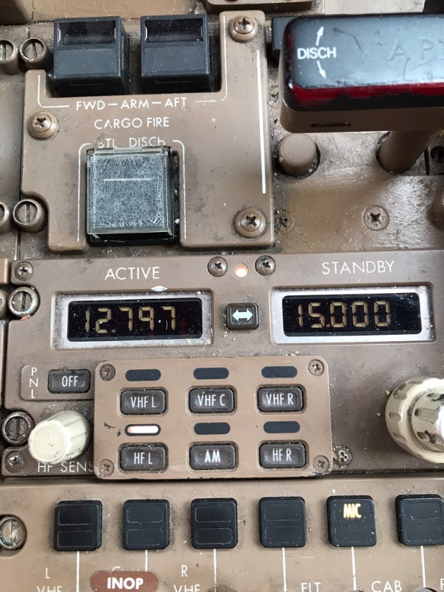
Frequency selection is accomplished from a panel in the cockpit.
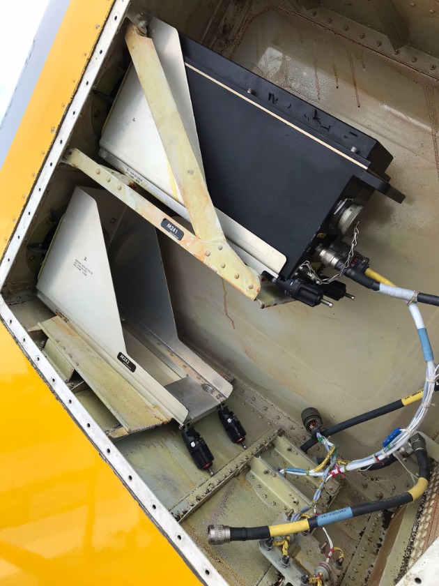
The RT (Receiver Transmitter) is located (on a 767) in the main equipment center. There is a tuning device called a coupler located inside the vertical stabilizer.

The antenna is actually part of the leading edge of the stabilizer.
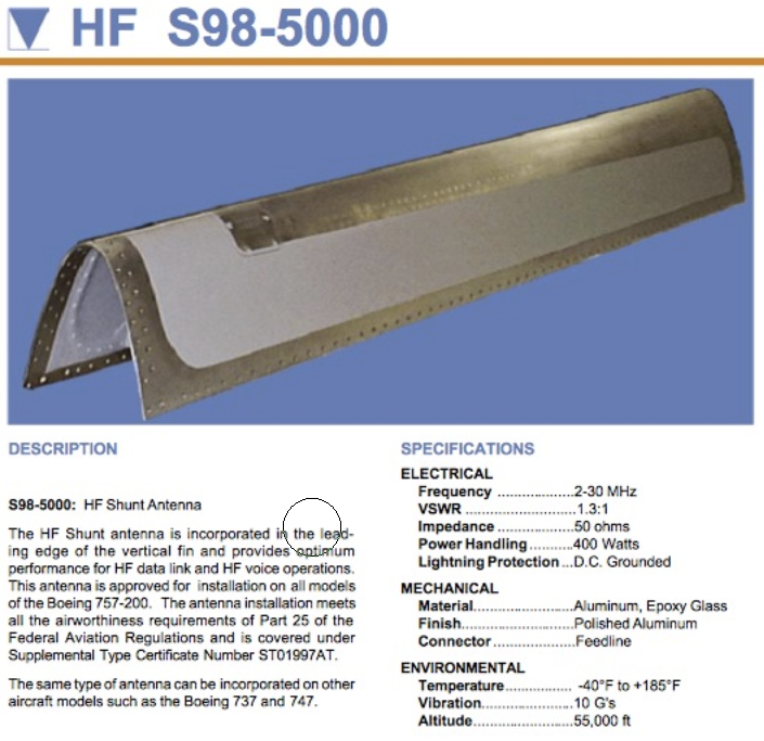
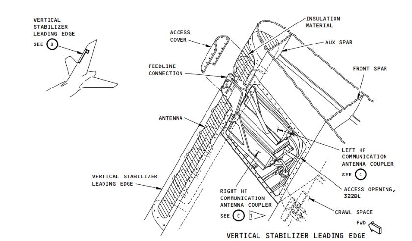
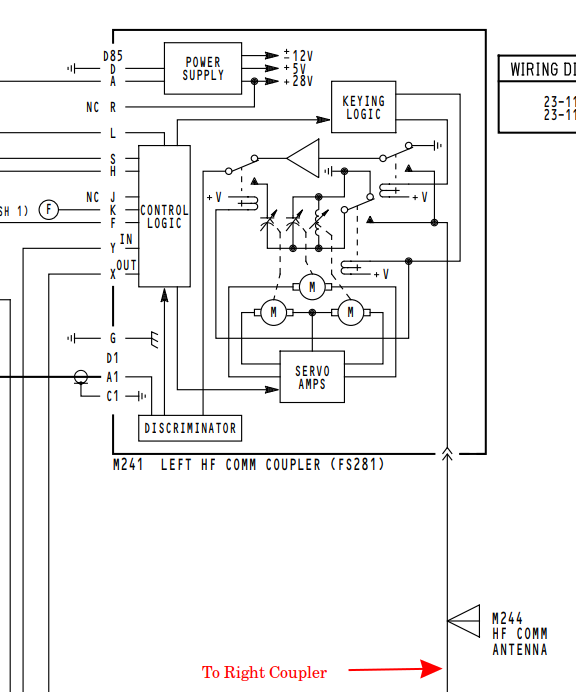
The coupler plays a significant part in the system as it "impedance matches" the R/T to the antenna for each frequency selected. As a note: antenna length is determined by frequency. The higher the frequency - the shorter the antenna. 1090Mhz (ATC, TCAS, DME antennas are about 2" high. VHF 118.000MHz - 136.975MHz antennas are about 18" long. The HF antenna is a fixed length, but HF frequency range is quite large. The coupler has three motors that drive two variable capacitors and one inductor which "tune" the antenna system for best transmission from the R/T.

When the panel frequency is changed and the microphone keyed, the coupler will begin to tune for the newest frequency. A tone is heard through the speakers or headset during this tuning cycle. After the tuning stops, actual communication can begin. The tune time is short for small changes to frequency (let's say 13.567 to 15.986) and longer for greater frequency range changes (3.456 to 20.876).
Tuning is not needed for reception frequency changes.
As with any multi-component system, failures can show up in different places, but a good 50%+ are coupler malfunctions. Although it is not exposed to weather, it is up in the tail and subject to vibration and extreme temperature changes. It has a 5psi nitrogen charge internal to the unit to keep out moisture. If that charge fails, the unit will..... shortly after.
When I approach an HF system failure, I'll go to the cockpit and check a few basics. Can I hear WWV (a series of "tics" with a tone at the top of every minute) on 2.5, 5.0, 10.0, 15.0 15.0 or 20.0Mhz? Lower frequencies at night - higher during the day. Does the system tune and how long does it take? Can I transmit to Collins Radio (New York or San Fransisco) [a phone call to them first is recommended as they will be listening for you and they will provide the best frequency to try]. Better yet, is there another aircraft on the field with HF??? Try that one first.
You "cannot" transmit from one radio to the other on the same aircraft. During transmission, the unused system is disconnected from the antenna to keep it's receiver from blowing out.
When the R/T swap doesn't fix your issue..... out comes the man-lift. With the coupler out of the rack, continuity to the antenna can be accomplished with the big center pin to ship's ground.
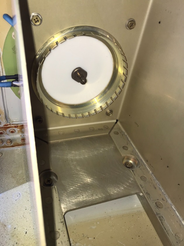
The co-ax can be continuity checked to the R/T rack connector with a jumper at the rack on the center pin attached to ground. A megger check can be done with the rack jumper removed (I usually get 9+ MΩ's at 250 volts, 8+ MΩ's at 500 volts, 7+ MΩ's at 1000 volts, center conductor to shield). The shield is connected to aircraft ground as a normal function so it needs to be checked at both ends (rack and coupler sides).
Enjoy the view while you're up there.....

Post is under moderationStream item published successfully. Item will now be visible on your stream.
Rotate Aero Users
Random acts of kindness are contagious!!
Don't have an account?
Register now to join the community!
©
2026
Rotate.Aero