| Volt/Ohm Meter |
||
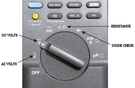
| All modern digital meters are capable of many functions. The majority of aircraft avionics/electrical systems troubleshooting is accomplished with four selections. | ||
|
Most systems use 115 VAC for power applications. Step-down transformers reduce this voltage to 26 VAC for signal voltage and 5 VAC for instrument or panel background lighting.
- - - - - - - - - - - - - - -
28 VDC is the standard direct current voltage. 28 VDC is commonly used for relay control, solenoids, and indication lights.
- - - - - - - - - - - - - - -
The resistance function is used for continuity certification of wiring. Internal component measurements are also checked with the resistance function.
- - - - - - - - - - - - - - -
Proper diode functions are verified with the diode check selection of the VOM. |
 |
|
|
Helpful Tips for Volt-Ohm Meter Usage
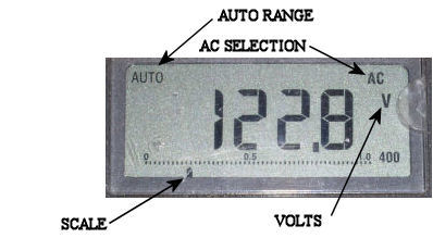
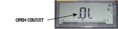
I usually like to leave a meter in "AUTO" mode for any checks that I am accomplishing. In auto it will indicate correctly no matter what the voltage or resistance might be. If you are using manual, the range must be proper for the system under test. Very often an "OL" is displayed when the meter is not in the correct range.
- - - - - - - - - - - - - - - - - - - - - - - - -
Having a meter with a backlit display is very helpful. More often than not, you can find yourself jammed in a hole with both hands busy holding test leads. Holding a flashlight in your mouth or having someone else to assist you is not needed. |
||
|
THE INFORMATION PRESENTED ON THIS SITE IS TO BE USED AS A GUIDE. APPROVED AIRCRAFT MANUFACTURER MAINTENANCE MANUAL PROCEDURES SHOULD ALWAYS BE FOLLOWED. |
||
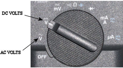
| Voltage |
||
|
The most common AC voltage systems on aircraft use 115, 26, & 5 VAC. Cycles are 400Hz. Normal power sources are 3 phase engine driven generators or inverters.
|
 |
|
 |
||
 |
||
|
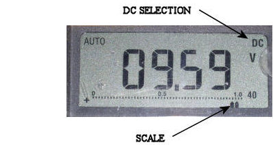
One helpful tip when checking power with a meter in AC or DC, is the scale at the bottom of the display. The sample rate for the digit display is not fast enough at times. If voltage is varying or intermittent, the scale is a better source for observing this problem. |
||
|
THE INFORMATION PRESENTED ON THIS SITE IS TO BE USED AS A GUIDE. APPROVED AIRCRAFT MANUFACTURER MAINTENANCE MANUAL PROCEDURES SHOULD ALWAYS BE FOLLOWED. |
||
| Resistance |
||
| Checking wire continuity or component resistance is a simple task. The majority of avionics/electrical troubleshooting requires the ability to decipher meter readings correctly. | ||
|
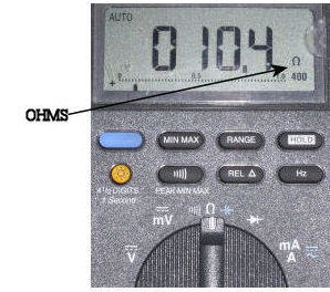
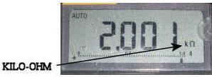
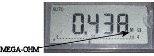
Particular attention to the Ω symbol when shooting electrical components is needed. The biggest mistake while using a meter is not observing the Ω, KΩ, MΩ indication. The display of .562 does not always represent ½ ohm, although I have noted this mistake many times. More than likely the meter is indicating .562KΩ or .562MΩ which is significantly higher than ½ ohm. The two readings above are 562 ohms and 562 thousand ohms, respectively.
Continuity checking a wire from the tail area to the E/E compartment of a 747 for example, can read numerous indications depending on wire condition. I tend not to get to excited about 25Ω or less. This would be a long run compared to most aircraft. The most common problem I have experienced while shooting a wire using ground as a reference, is the ground itself. Using a poor ground connection on either end can give a bad indication for a wire that is likely good.
I tend not to use the buzzer function of the meter for wire checking as verification of a good wire. Direct observation of the meter reading is recommended. |
 |
|
 |
||
 |
||
|
Helpful Tips for Component Resistance Readings
Closed relay contacts and plug contacts should be as close to 0Ω as possible. Other components such as solenoids and sensors will have higher readings. Many of the correct values for such components can be found in maintenance or troubleshooting manuals. Most parts are duplicated on aircraft. Sometimes comparison to a known good component is helpful.
|
||
|
THE INFORMATION PRESENTED ON THIS SITE IS TO BE USED AS A GUIDE. APPROVED AIRCRAFT MANUFACTURER MAINTENANCE MANUAL PROCEDURES SHOULD ALWAYS BE FOLLOWED. |
||
| Diode Check |
||
| Checking wire continuity or component resistance is a simple task. The majority of avionics/electrical troubleshooting requires the ability to decipher meter readings correctly. | ||
|
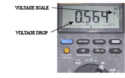
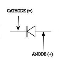
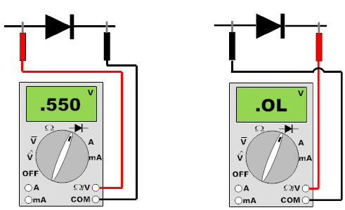
Diodes are solid state devices used extensively throughout aircraft avionics and electrical systems. They are basically a "check valve" for electrical current, allowing flow in one direction only. To verify the condition of a diode, one leg should be isolated from the system. Having the test leads in the forward bias position the meter will read the voltage drop across the diode (the meter displays "V" instead of "Ω"). Typical indication is from .5 to .6 volts. With the leads swapped, the meter will read open. The easiest way to remember the bias, the diode "points" to ground or negative. The diode will have a white band on the negative side.
Some sensors installed on aircraft have diodes installed in "series" with resistors. Fuel level sensors are an example. When checking these from the fuel level amp, the meter will have to be selected to diode check to verify proper continuity of this type of sensor.
There have been many times that I have been continuity checking wires only to have the resistance reading jumping around in the 1MΩ range. If this is noticed, flip the meter to diode check to verify if one is in the system. Schematic diagrams often omit showing diodes that are installed. |
 |
|
 |
||
 |
||
 |
||
 |
||
|
THE INFORMATION PRESENTED ON THIS SITE IS TO BE USED AS A GUIDE. APPROVED AIRCRAFT MANUFACTURER MAINTENANCE MANUAL PROCEDURES SHOULD ALWAYS BE FOLLOWED. |
||
| Test Leads |
||
| Checking wire continuity or component resistance is a simple task. The majority of avionics/electrical troubleshooting requires the ability to decipher meter readings correctly. | ||
|
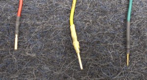
Troubleshooting aircraft systems requires access to plug and rack pins. Having a set of different size test leads is essential. Safety wire is not a practical tool for testing circuits.
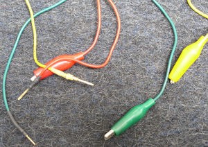
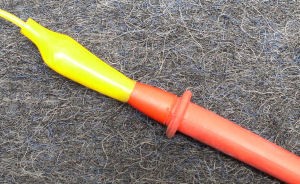
I use test leads that I made from Radio Shack® alligator clip jumper wires. I cut them in half and crimped various size pins on them. I use heat shrink tubing to protect all but the working end of the pin.
I ground down the tips of my meter test leads about ¼" to accommodate the alligator clips. When I hook up to the meter lead, I push the rubber of the clip over the plastic of the lead. This prevents inadvertent grounding of the alligator clip on metal. It's always nice to see that split second of flash and spark, then be left wondering what you just fried.
I like to have at least two each male and female sizes in the red (20) and blue (16) gauge pins. Digital computers use smaller pins in the 24-26 gauge range. The males in this range are easier to obtain because the rack plugs use them. The females are not easy to find, they are on the computer (LRU) plugs. The component shops have them, but line mechanics do not normally have access to these. The problem is, the females are needed to get into the rack pins for troubleshooting. If you find any females in this smaller size, take care of them.
- - - - - - - - - - - - - - - - - - -
If a plug with bent male pins is found, try using a female pin to straighten them out. It is a lot easier than a screwdriver or needle nose pliers. |
 |
|
 |
||
 |
||
|
Just as a note: Always continuity check your test leads before using them. They do wear out and go open. I've been caught many-a-time using bad or on the fringe test leads, it can cost you hours of work. |
||
|
THE INFORMATION PRESENTED ON THIS SITE IS TO BE USED AS A GUIDE. APPROVED AIRCRAFT MANUFACTURER MAINTENANCE MANUAL PROCEDURES SHOULD ALWAYS BE FOLLOWED. |
||