Rotate Aero
  • Home
  • Forum
  • Blog
  • Community
  • Contact
  • Search the Site

   
Megger 


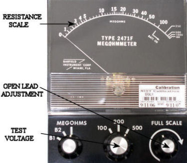
The Megohmmeter or Megger is a great tool for verifying wire to ground or wire to wire shorts. It applies a high voltage DC potential across the wire(s) under test. The megger will show shorts that would not be known using a regular Volt/Ohm meter.


The ABSOLUTE first step before using a megger is to verify per the wiring prints that ALL associated components have been isolated from the wire under test. Neither analog nor digital circuitry enjoy 250-1000 VDC being thrown at it and most components will not survive a hit from a megger.


Never use a megger to verify a “in tank” fuel quantity harness problem.


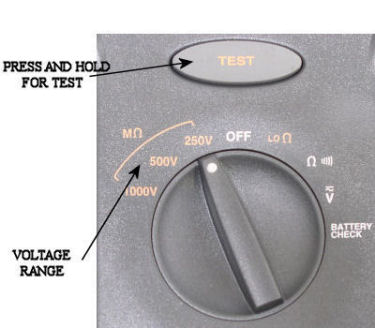
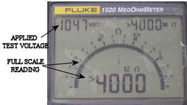
Digital meggers do not require any adjustment to use. Older analog units have an open lead (tests leads not connected) full scale adjustment. Adjust this to maximum or infinity (∞) before use. This adjustment will change with the different test voltages.


I like to start at the lower voltage settings to check wires. A megger will supply a high voltage potential, but very little current, it is still good practice to start low and then move higher if needed. A good check indicates as close to maximum (∞) as possible


megger3

 megger1
 megger2


Tips for Megger Testing

  1. Wire shorts can occur anywhere throughout an aircraft. I have found that most are outside the pressure vessel, in high vibration areas. Wings, pylons, and the horizontal stabilizer areas are prone to wiring problems.
  2. A megger will show that there IS a problem. Finding it can be difficult at times. Isolation by eliminating wire sections is good practice. If possible, narrow the area down to between two plugs with no other connections inline.
  3. Some shorts require two people for troubleshooting, one to watch the megger and one to shake down the suspect area.
  4. Watch where your fingers are. Most people do not forget a megger blast


THE INFORMATION PRESENTED ON THIS SITE IS TO BE USED AS A GUIDE.

APPROVED AIRCRAFT MANUFACTURER MAINTENANCE MANUAL PROCEDURES SHOULD ALWAYS BE FOLLOWED.


Fuel Quantity Test 
     
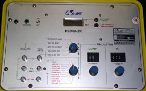
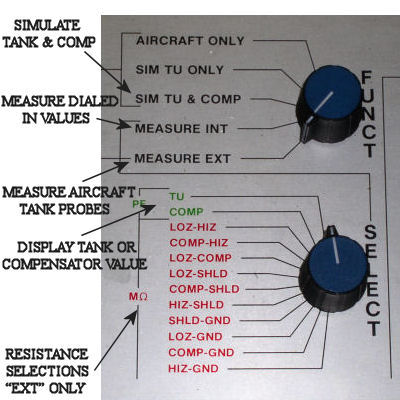
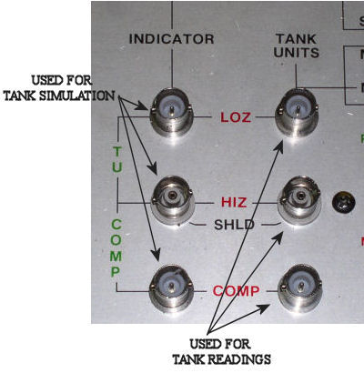
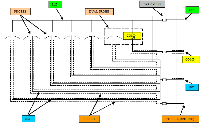
Aircraft fuel quantity indications are capacitance based systems. Troubleshooting and calibration of these systems is accomplished with the Fuel Quantity Test Unit. The tester measures tank and probe capacitance, accomplishes resistance checks, and provides simulation for tank quantity indication.


STARTING WITH THE BASICS


  1. Most aircraft fuel tanks have numerous fuel quantity probes installed. The number of probes used can vary depending on tank size and system design. Most common configurations have 6-12 probes. These probes are arranged in a parallel circuit.
  2. Each probe is a capacitor. The capacitance value of the probe will change with fuel level changes. The higher the fuel, the higher the capacitance.
  3. The input signal that feeds all the probes is called LoZ. The output of the probes is referred to as HiZ.
  4. Fuel capacitance is read in picofarads or pf.
  5. Capacitance in a parallel circuit is additive.
  6. Tanks have one probe that measures fuel density. This is the Compensator Probe. The “comp” probe has a unique function, but its output is still read in pf.


FUEL TANK CAPACITANCE CHECKS


Fuel quantity test boxes are made by numerous manufactures. All will have similar switches and functions. The tester shown here is JcAir® “PSD60-2R.
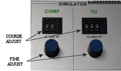
  1. Tank capacitance checks are run with the mode selection in MEASURE EXT.
  2. Each aircraft type usually has a breakout box with all the matching plugs to connect to either the spar plug or indicator. Breakout box connection configurations will differ for aircraft type, but all will have the same outputs for the fuel quantity tester. The co-ax connections are HiZ, LoZ, and Comp (numerous breakouts have only HiZ and LoZ, the Comp is included with the rotary switch selections).
  3. If the test setup is connected at the indicator, only total tank and compensator readings can be made.
  4. If the breakout box is connected at the spar plug, each individual probe can be measured along with total tank readings.
  5. Tank or probe readings can be done with meter test leads, but the hookup requires having the correct spar pin-outs. Using the proper breakout box is still the preferred method.
  6. The fuel quantity unit’s TANK UNIT co-ax (BNC) connections are differentiated by gender. LoZ and Comp are male pins. This reduces the chances of incorrect setup (if the LoZ and Comp are swapped, you’ll know it).
  7. Tank or probe capacitance readings will not be correct if the ground leads from the fuel quantity tester to the breakout box and from the breakout box to aircraft structure are not connected.
  8. All tank and probe readings need to be made with the tank completely empty. Some tanks will require sumping. The Comp probe is located at the lowest point, if it is still sitting in fuel, the capacitance reading will be high.
  9. Total tank and probe capacitance values can be found in the aircraft's Maintenance Manual.
  10. A major function of the fuel quantity unit is measuring insulation resistance or a “Meg Check”. Different combinations of shorts can be detected. Minimum values for meg check readings will also be found in the M.M.


  TANK SIMULATION


  1. Simulation of tank values is used for troubleshooting of indication systems. It is also used for calibration of some types of fuel systems. For calibration purposes, the simulated value is used along with the tank to adjust the “full” value of stand alone indicators.
  2. Tank simulation is a two step process. The simulation values need to be set up first and then the box switched to simulate mode.
  3. All simulations use the INDICATOR co-ax plugs. LoZ, HiZ, and Comp require correct connections.
  4. Simulation values are set with the mode select switch in MEASURE INT.
  5. Tank unit and comp values are dialed in with the course and fine settings of the tester. The thumbwheel indication does not match actual values. The display should be monitored when setting both tank and comp.
  6. After the values have been set, the select switch is placed in SIM TU & COMP. The unit will output the dialed in values and the screen will show dashes or eights.
   
   fq1
   fq2
   fq3
   fq4
  fq5 1


Helpful Tips for Fuel Quantity Testing


  1. Fuel quantity indication problems can be located anywhere in the system. I will exhaust ALL avenues before opening up a fuel tank for troubleshooting. Been there, don’t want to go back. Only a bad probe reading or failed meg check from the spar plug would be cause for accessing the tank.
  2. Meg checks usually verify problems with the tank harness. Fuel can migrate into an older harness and cause shorts in the wires. Probes rarely, if ever short out.
  3. A low or nonexistent probe capacitance reading is normally caused by a bad connection of one probe terminal. This connection must be made properly (screw, washer, terminal, and then probe) and it must be secure.
  4. It is not unusual to have probe readings that are slightly (+/- 5pf) out of M.M. tolerances. These reading are normally on the high side. When a tank is drained of fuel, some will remain on the walls of the probes.
  5. Simulation of tank fuel quantity from the spar plug to the aircraft is useful for troubleshooting non-tank related problems. Empty tank simulation can be easily accomplished. If “fuel on probes” simulation is needed, I use the opposite wing tank values for HiZ and Comp. Simulating these values for whatever fuel level needed must be correct. The Comp, once it is wet will stay the same for all quantities. The HiZ will vary with fuel level. If either is not simulated correctly the aircraft fuel indication will most likely show an error.
  6. Newer generation aircraft send tank quantity signals to a central Fuel Quantity Computer. Each tank quantity is calculated and sent out via 429 data bus to all the systems requiring quantity information (EFIS, FCC, TRC …etc).
  7. Douglas products incorporate a junction probe that can be accessed from the top of the wing for isolation of probe or harness problems.
  8. MD-11’s or any other aircraft that allows making one tank probe inoperative from CFDS use a different type of quantity computation. They do not add capacitance. All probes are monitored individually. A modified average value is taken for quantity calculation. Loosing one probe will make the system less accurate, but a reliable quantity is still available
     
     
  fq8
     

THE INFORMATION PRESENTED ON THIS SITE IS TO BE USED AS A GUIDE.

APPROVED AIRCRAFT MANUFACTURER MAINTENANCE MANUAL PROCEDURES SHOULD ALWAYS BE FOLLOWED.


Watt Meter 


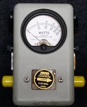
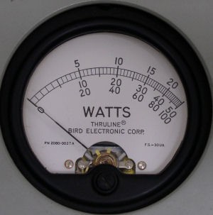
The Watt Meter is used to verify the operational integrity of VHF and HF transmission co-ax and antenna systems. It checks forward and reverse power of audio transmissions. The indication result is often referred to as SWR or Standing Wave Ratio.


Aircraft voice communication radios, VHF (118.00MHz – 136.00MHz) and HF (2.0MHz – 29.9999MHz), require the transmission system to dissipate the maximum amount of the transmitted signal. No system is perfect, so there always will be a feedback of some of the signal. If this feedback is within acceptable minimum limits the VHF and HF transceivers will provide proper communication functions. When the co-ax or antenna installation as been compromised, the majority of the transmitted signal will not be radiated from the antenna. This power must go somewhere, so it will travel back down the co-ax to the R/T. The flight crew will report poor or inop transmissions. If the problem is not found and corrected, the result will be numerous R/T replacements and continued pilot write-ups.


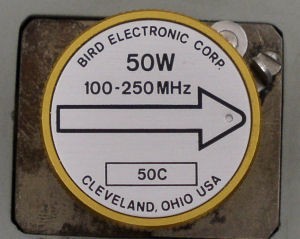
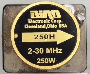
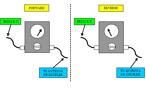
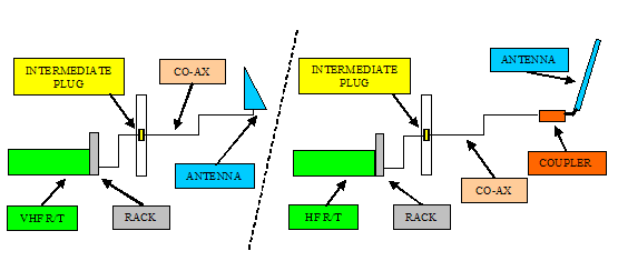
The watt meter is placed "in-line" with the co-ax run. Placing it in the system requires one or two extra co-ax jumpers and a connector adapter kit to match the jumper(s) with the different types of aircraft connectors. It also requires the correct "slug" to be installed in the meter. For VHF, the slug is usually 100MHz – 250MHz with a 25 -50 watt rating. HF slugs are 2MHz – 30MHz with a minimum of 200 watt rating. The arrow on the slug "points" down line towards the antenna for forward power and to the R/T for reverse power. With the affected radio selected and microphone keyed, the forward or reverse power can be measured. Typical aircraft VHF radios output approximately 15 watts. HF radios transmit around 150 watts.


 bird1
 bird2
 bird3  bird4


Helpful Tips for Watt Meter Usage

  1. Placing the meter in-line with VHF systems can be accomplished at an intermediate plug break that is usually in the electronics compartment, or directly at the antenna. HF's might have a plug break, but the easiest insertion point is right before the coupler. The R/T rack plugs do not allow for system breakout.
  2. Meter readings are arbitrary. A working system should have the reflected signal well less than 10% of the transmitted signal. 5% or less should be considered normal. A faulty co-ax or antenna will result in a much higher reflected reading.
  3. HF systems have extra components for antenna usage. The coupler is a tuning device composed of variable capacitors and inductors that "tune" the antenna for a selected frequency. The tuning process is indicated by a tone output on the speakers immediately after the microphone as been keyed. Watt meter readings should be accomplished after the tuning has completed. The system will repeat this process any time the frequency is changed.
  4. HF systems share the same antenna (not all the time). An isolation relay is used to protect (disconnect from the antenna) the unused R/T while the other is transmitting. This is accomplished at the back of the coupler rack. The watt meter cannot be used anywhere "aft" of the coupler.
   
   
bird5
   
bird6  
   

THE INFORMATION PRESENTED ON THIS SITE IS TO BE USED AS A GUIDE.

APPROVED AIRCRAFT MANUFACTURER MAINTENANCE MANUAL PROCEDURES SHOULD ALWAYS BE FOLLOWED.


Buzz Box 


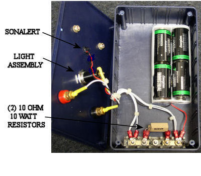
A buzz box is used to apply a current load on a wire. A wire that is hanging on by a couple threads will check good with a ohm meter, but it might not be able to carry the required load.


A buzz box can be built to apply almost any amperage. The box shown here will put approximately 1 amp across a wire. A 22 gauge or larger wire can safely handle 1 amp for testing. 24 gauge wires, which are about the smallest installed on aircraft, are mainly used for signals. Putting 1 amp across a 24 gauge wire is not a good idea. On the rare occasion where a larger wire needs to be loaded, aircraft bulbs used with 28 volt battery power are a good way to load a wire. Medium sized bulbs such as a runway turnoff or wing illumination light will put a hefty load on a 14-16 gauge wire.


The buzz box or light is going to accomplish one of two things, either the wire will carry the load or it will burn through. If a wire goes open, it is easier to find and correct the problem.


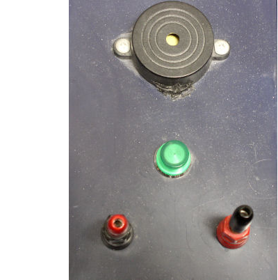
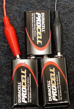
All the components for this box were purchased from Radio Shack®. The resistors, light, and sonalert are wired in "series". The wire under test completes the circuit.

 buzz1
 buzz2
   

THE INFORMATION PRESENTED ON THIS SITE IS TO BE USED AS A GUIDE.

APPROVED AIRCRAFT MANUFACTURER MAINTENANCE MANUAL PROCEDURES SHOULD ALWAYS BE FOLLOWED.


Easy 28 


It might look cheap, but if a quick supply of 28 VDC is needed, it works great. This is mainly used as a "off aircraft" tester for relays, solenoids, and bulbs. Power is limited, using it on larger items is not recommended.


Having a bench 28 VDC power supply available for testing is still the preferred method.


See it in action!!

 28vdc


THE INFORMATION PRESENTED ON THIS SITE IS TO BE USED AS A GUIDE.

APPROVED AIRCRAFT MANUFACTURER MAINTENANCE MANUAL PROCEDURES SHOULD ALWAYS BE FOLLOWED.

     
  1. Wire Tracer

Page 2 of 2

  • 1
  • 2

Rotate Aero Users

  • Eversolenick1
  • dynamics
  • OG GarlicSalt
  • peter.waters01
  • Scorpio47
  • Khelifisouf
  • JoeBlow
  • Emblemdhc
  • John
  • cwaddell
  • jake ounce
  • edoradar
  • minhas1
  • mrbell52
  • yasay

Random acts of kindness are contagious!!

Don't have an account?
Register now to join the community!
© 2025 Rotate.Aero
  • Thor's Hammer
  • Stats
Login
  • Register for an account
  • I forgot my username
  • I forgot my password