| ILS Test |
||
|
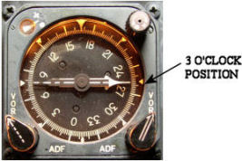
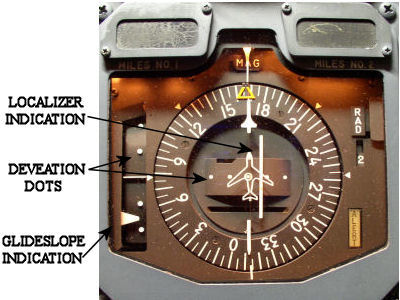
The ILS or Instrument Landing System is a landing aid used to provide the correct lateral and vertical angles to the end of the runway. Glideslope and localizer information displayed with the deviation indicators is referred to as "raw" data. The navigation receivers provides this information. Additional outputs from the receivers are sent to the autopilot and flight director computers for "coupled" approaches. The flight director computer or FCC uses ILS data along with other inputs such as air data and radio altitude for display on the ADI flight director as "computed" data.
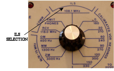
Testing the ILS system is accomplished with the VOR/ILS test box. Many different varieties of test units are used today. The basic functionality of them is the same. Most units use 108.10 MHz as a standard test frequency. This is actually the localizer frequency, but a matched glideslope output is also transmitted.
Tuning the aircraft's navigation control to 108.10 will place the receiver in ILS mode. If an aircraft is equipped with dual systems, placing both controls to 108.10 is helpful as a comparison of indications. Newer generation aircraft do not have a navigation control. Tuning of the navigation receivers is accomplished by the Flight Management System. Manual tuning is possible from the FMS control head. Honeywell FMS's have a line select key labeled NAV/RAD for inputting frequency and radial.
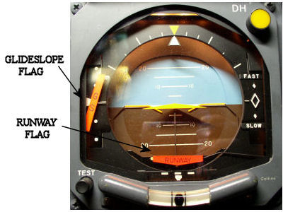
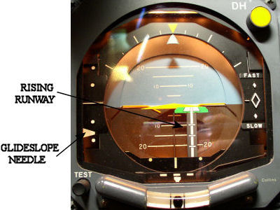
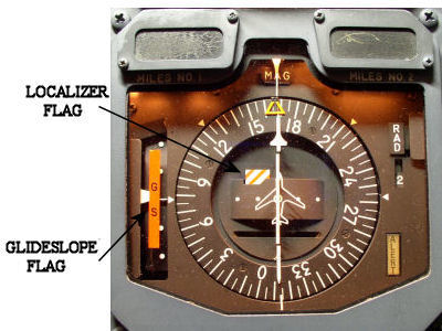
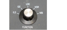
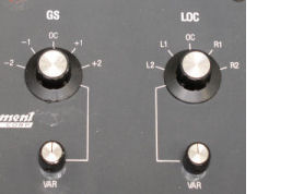
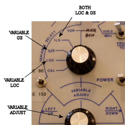
Select ILS on the test box. If the proper output is received, both the localizer and glideslope flags should pull out of view. Most testers allow for separate control of localizer and glideslope signals or both can be driven simultaneously. Full scale defections of either needle should be noted when the vaiable knob of the tester is used.
|
|
|
|
|
||
 |
||
 |
||
 |
||
|
|
||
|
Helpful Tips for ILS Indication and Testing
|
||
|
THE INFORMATION PRESENTED ON THIS SITE IS TO BE USED AS A GUIDE. APPROVED AIRCRAFT MANUFACTURER MAINTENANCE MANUAL PROCEDURES SHOULD ALWAYS BE FOLLOWED. |
||
Rotate Aero Users
Random acts of kindness are contagious!!
Don't have an account?
Register now to join the community!
©
2026
Rotate.Aero