Search Results (Searched for: splices pin)

02 Apr 2025 14:16 - 02 Apr 2025 14:43
Replied by Mark on topic Installation of wires
12 wires total. The pins called out are "only" for the plug on the right.

The other side of the wire group goes to different type plugs (which might have different pins).

Those pins must be identified in the Standard Wiring Practices Manual.

I see three jacks and the left and one plug. I know they don't use the same pins.

They could be male or female. Larger or smaller diameter.....

This post:  Pins/Splices/Terminals     Might help you out.


Direct Link rotate.aero/images/Basics/Tools_Pins_Sockets_Term.pdf


25 Nov 2024 03:53 - 25 Nov 2024 17:40
When dealing with larger generator feed wires, splices, pins and terminals require special hydraulic crimpers. I'm not an expert at the Standard Wiring Practices Manuals. For me, looking for the proper tooling can be difficult.
As a way to help myself (and others) is to make an entry on every repair and the tooling we used to accomplish the job.
  
APU Generator To Firewall Plug


We used crimp die 11738 on both ends.
Crimper base 13642M
Pump 69120-1
 
The following images are just for reference....


19 Apr 2024 13:48
I'm still trying to get the flow of this.

Is Nav Tuning from the Garmins or is there separate Nav Control Units?

If the Garmins are tuning, it looks like those tuning requests go to the DME Master Indicator (KDI-574) on pins 11, 12 and the J-Box on 70, 51. from there the J-Box feeds the request to the DME (KN-63)  on pins F, 6. The DME output goes back to the J-Box which feeds the Arinc Adapter (KDA-689) which outputs 429 data back to the GNS (I only see an output to the left unit).

If I'm correct, this still leads back to a tuning issue from the #2 (or right) GNS. I circled some wires to check on a previous post. The "RNAV REQUEST" signal from each Garmin looks to be the signal which tells the Master Indicator which side (GNS request)  to forward to the DME.

If those four wires (18, 19, 20, 22) check good from the #2 GNS..... the Master Indicator would be the most suspect unit.

Also, three of those wires are connected to each other via splices. To make sure one Garmin isn't loading them down, try each alone with the other GNS not in the system. In your case.... disconnect the #1 GNS to see if the #2 tunes and displays properly.
05 Apr 2023 12:47 - 05 Apr 2023 12:54
Replied by Mark on topic Electrical wiring monitoring
I guess you could map (record) an image of the wires in a normal working condition with a TDR, but I really don't know if that will help in the long term.

If any systems that needed to be verified in a working condition..... it would be the co-ax wires to all the antennas.

If you really wanted to record the three phase wiring to your fuel pumps there would be no need to splice in anywhere. You could disconnect the wires from the power relay and shoot back towards the pump or tie-in at the disconnect plug just downstream of the relay.

Your TDR display should show a slight bump for the splices and then go straight down (indicating a short) when the signal hits the pump. If the plug is off at the pump, the line will go up indicating an open.

The total wire distance to the pump could be noted also.


When we have pump wiring issues..... we first check continuity with the VOM and then we hit it with a  Megger to show us if we have a short to ground or wire to wire.

If you had a previous mapping of the wire, the TDR would certainly show the approximate location of the problem.
26 Mar 2023 18:43
Replied by Mark on topic B737 boost pump wiring
Most (if not all) Boeing fuel pump plugs are front release. They use a blue push-out tool as explained  here.

I wouldn't be pulling any wires through a conduit without a pull wire attached. That way, the new wire bundle can be pulled back through the conduit with the pull wire.

You shouldn't have to pull the pump. Your wires are external from the tank itself.

I guessing this whole modification deals with suspect wiring (possibly Kapton ) installed for the pumps. The AMM only allows the two types of wire. Problem is..... if the wiring is original, you might not be able to read the wire part number printed on the outer sheathing. If it cannot be identified or the wrong part number is installed, it must be replaced.

It looks like they would allow splices between vapor and pressure seals. It states the original splices are inside the pressure vessel.

I have no idea what the difference is between the splice types, but they obviously will allow either type.

Two sleeves, one long - for the wire run, one short (to be placed right behind plug) to be marked with the plug identifier.

As far as the plug goes..... I would replace them. Although not directly in the weather, they are exposed to continual heat/cold cycles. The rubber gets hard and cracks which will possibly let two pins touch each other.
13 Apr 2022 07:22 - 13 Apr 2022 07:24
Orange in-line splices and pins.

Splice P/N  TSE-20-01 ( Reference )

Pin P/N 1841-1-5620 ( Reference )


06 Jul 2018 22:50 - 08 Jul 2018 15:25
Freon Air Conditioning was created by Mark
Citation Bravo with an A/C compressor that was not coming on. The cabin blower fans (fore and aft) did come on with A/C switch selected on.

The compressor unit is quite the pain to access, much less troubleshoot. It's tucked in the forward right section of the hell hole. It is mounted quite low also. The majority of the electrical components are mounted underneath the unit and are only freely accessible with the whole unit pulled out and laying on a bench. This problem didn't require such drastic measures.

The compressor system uses a control unit to power a large contactor which feeds 28 VDC to a compressor motor. This motor has a large drive belt which spins the actual compressor.

Without access to the maintenance manual, some basic control logic functions can be understood. The controller needs to see the aircraft on ground using external power. It also requires a 28VDC signal from the cockpit switch. There are inputs from the generator system, but their function is unknown. If all the prerequisites are satisfied, the control unit sends an enable signal (28VDC) to the compressor motor contactor.

Initial troubleshooting just required an ear. A noticeable "click" was heard when the cockpit switch was cycled a few times. This of course, required two people. The click was quite faint while listening directly in the hell hole. This was actually a small relay inside the controller which when closed, fed 28VDC out on the "enable" wire.

With that being understood, it was now time to determine if or why not voltage was reaching the contactor coil. An easy way to accomplish this was the hour meter. The red wire feeding the hour meter is tied off of the coil input enable signal. No voltage was found. Just to check the main power feed from the 135 amp breaker was present, it could be checked via the hour meter's white wire. Power was present on the white wire.


This left only two intermediate pressure switches as a possible problem. A barometric switch and a freon pressure switch are wired in series to the contactor coil. I have no clue as to what the baro switch is used for. The freon switch is mounted on top of the receiver-drier in a horizontal direction.


I was very lucky that the wiring was easily accessible to the freon pressure switch. After sliding back the heat shrink, voltage was found on only one of the connectors ( knife splices ). The open pressure switch was bypassed for just a brief second with a jumper wire. The contactor closed and the motor started running.

Switch replacement required a purging of the freon before removal and a re-service after a new one was installed.


Cessna A/C System WDM C30062
26 Sep 2017 13:52
Landing Gear Control was created by Mark
I recently had a three day ass-kicking on a Cessna 421 gear system that was popping the control breaker whenever the gear handle was placed in the up position. The system uses two switches on each gear and all three systems are wired in parallel. We had a short in the right wing disconnect plug, but the problem could not be truly isolated until all gear wiring was separated by individual gear. This involved physically tracing wires in the nose and under the instrument panel. This aircraft model uses "splices" instead of terminal blocks. Finding those splices was a REAL pain.

Otherwise, some learning was accomplished: A hydraulic selector valve and a hydraulic load valve are used to retract and extend the gear. From my best guess, the load valve (supplies pressure) is used for both up and down. The selector valve appears only to be used in the up direction. I'm assuming that when the solenoid is powered on the selector valve it pushes on a spring that normally keeps the valve porting fluid for a gear down condition.

Wiring depicted in the 421 maintenance manual.


Condition when gear handle selected up.


Gear up and locked when gear handle selected down.

01 Aug 2017 11:29 - 01 Aug 2017 11:31
Environmental Splices was created by Mark
Environmental Splices should be used anytime a splice is needed outside the pressure vessel. This type of splice should also be used if there is any chance of liquid exposure.


The splice is composed of two parts, the inner barrel, and the outer sleeve. The barrel provides a solid wire to wire connection. The sleeve has sealant on both ends. When heated, the sealant flows around the wire and the sleeve body shrinks. The splice completely isolates external elements to greatly reduce the chance of failure over time. Environmental splices are manufactured by Raychem®, they require the correct crimper be used.


Quick Notes for Environmental Splices

  1. The AD-1377 crimper is used for barrel crimping. It places a double crimp on each side of the barrel.
  2. The crimp depth is important. The tool might need adjustment; the barrel as a tendency to bend along the length if the crimp is too tight.
  3. The placement of the color stripes on the barrel and sleeve are used for a reference only. It does not matter if they are matched.
  4. A good heat gun is needed. Having a curved tip adapter is also helpful. A considerable amount of heat is needed to allow for sealant flow. Portable heat guns normally do not have enough heat or flow. Butane torches will burn through the sleeve before sealant flow, they are not recommended.
  5. A good splice is characterized by two solid crimps on each wire and complete sleeve shrink with sealant flow on both sides.
01 Aug 2017 10:35 - 01 Aug 2017 10:37
Terminals and Splices was created by Mark
Wire repair often requires the use of terminals and splices. The proper crimping procedures and instructions for tool use are covered in the aircraft Wiring Practices Manual. Terminals are used extensively for aircraft frame (ground) connections and terminal strip interconnects. Splices are normally used for wire repair. The use of "exposed" splices is limited to areas inside the pressure vessel with no chances of chemical (Skydrol®) contamination.


All terminals and splices are designed for double crimps. The crimp on the wire insulation provides tensile strength. The crimp on the wire itself is for electrical conductivity. To long or short of a wire strip will decrease the effectiveness of the connection.


Proper placement in the crimping tool is also needed. A terminal or splice that has not been positioned correctly will most likely be bent out of shape. Crimping tool damage could also result. Once the first "click" is heard while crimping, the tool must finish the cycle before the crimp head will open.


Quick Notes For Crimping

  1. Color codes for wire gauge are standard for all aircraft usage. Yellow 10-12, Blue 14-16, and Pink/Red 18-22.
  2. The inserts shown with the splices on this page allow for two different wire gauges to be connected together. The blue insert fits into a yellow splice and the red insert fits into a blue splice
  3. The tool, terminals, and splices shown here are commonly used on aircraft manufactured in the United States. Airbus® aircraft have a slightly different style and material for their terminals. A specific tool is needed for crimping these, but a double crimp is still the result.
  4. Crimping tools will have an alignment bar for placement. Splices will have a notch that fits under this bar. Terminal lugs also go under this bar. If the terminal is positioned correctly, the bar acts as a "stop" for the wire as it is inserted.
  5. A good splice is characterized by the two crimps at the correct locations and wire visible through the inspection window at the midpoint of the splice.
  6. A good terminal connection will have two properly placed crimps along with the wire visible on the lug side of the terminal.
  7. Automotive crimpers and channel lock pliers are not proper for aircraft terminal or splice usage.
01 May 2017 08:40 - 05 Nov 2017 12:54
Replied by Mark on topic Short Wire In Plug
rotate.aero/forum/wire-works/250-environmental-splices

A service loop is just an extra 3-4 inch section of wire looped around (like an oval) with the new pin and splice. There is no way to splice in a wire length to match the others. You'll just have the repaired one longer....... that's why you loop it around.

The only other option is to shorten and re-pin "every" other wire to match the length of the wire in question.

Now...... if you already have a few loops, maybe a complete re-do would be in order.
12 Feb 2017 23:47 - 13 Feb 2017 00:06
ATA 33, Panel Lights was created by Mark
Sometimes it's best to reference the wiring prints "before" troubleshooting.

In this case some simple panel lights turned out to be quite a learning experience.

The crew was reporting that this particular panel located lower left on the co-pilot's instrument panel was not illuminating.


No biggie, right??? Well, most of the panel lighting I've come across is pretty simple. Almost all commercial aircraft use 5VAC and corporates use 28VDC, 5VDC, or 5VAC.

I dropped the panel, dug out the terminals and shot for voltage.


Nothing on the red wire and a "backwards" 28VDC on the black one. With the "EL" knob full CCW (dim), I had 28 - full CW, 0 VDC......WTF???


I pulled out a pin and shot the panel itself for continuity...... open. Bad panel I guess.


While looking for a part number, what do you suppose surprised the shit out of me??


115VAC...... What? I then asked for a print. After a perplexing study of it, I discovered that Cessna uses 115VAC panel lighting for "some" of the lights and 5VDC for the rest. It doesn't make much sense, but a change of direction was needed. With the meter on AC, I had 30VAC with the knob in dim and 60VAC with it turned bright. OK...... that matches what the print is showing, but I was only using DC external power, where's the AC coming from?

There are 4 "inverters" as they call them on the print. As far as my mind goes, inverters change DC to AC. They're "all" labeled as inverters. In reality, only one is. The other three only vary the DC output. Should they be called inverters?


I really didn't give a crap because the panel was showing open. Either AC or DC...... it should show continuity. A replacement fixed the problem.

As a note....... it seemed that all the lower panels on the pilot's, co-pilot's, and center panels use this AC voltage for lighting. The circuit breaker panel lighting also uses it.

Still though...... almost 30 years doing this shit and I got me a little smack on my pride.


Cessna 550 Bravo
AWM 33-10-02
30 Oct 2016 14:09 - 30 Oct 2016 14:34
I didn't know if this should be put here or possibly starting another Gulfstream topic dealing with just wiring.

Oh well..... this really concerns "old" wiring no matter what aircraft types we're talking about.

This particular GII's problem was not having the "Start Valve" master caution light on when the #1 engine was being spooled up.

Simple-ass circuit, but you sure couldn't see it through all the possible ASC options shown on the wiring diagram.

The switch on the start valve only has two output pins.


Pin "A" is 28VDC coming from (depending on ASC) either the #5 master caution breaker near the floor of the 169 panel (the right engine uses #7) or a separate breaker in the cockpit. Pin "B" is the feed to the master caution, "Left Start Valve" light.

What is the easiest thing to try first???? A jumper on the plug to rule out the start switch itself (even though maintenance had already stated a replacement starter was tried).


No light with the jumper in. Out came the meter. No voltage on pin "A". Shit, now what? Well, the most likely problem would be in the plug...... so let's open it up.


Hey a busted pin!!!
First of all, I haven't seen one of these types of pins in well over 15 years. The last being a 727 firewall plug. The pin actually comes out forward and it is held in by a removable pink plastic ring. Old-old-old technology, but it still needed to be fixed.


After digging through my stash, a replacement pin was installed. Did the light come on???? No.

And here is where the point of this whole post is. "I" broke the wire off the pin when I opened the plug up. Yes, it probably was on the fine line but, it wasn't the problem. The actual problem was an open section of wiring on the other pin about 4" up from the pin itself. Knowing that this was quickly turning into a cluster, we found a replacement plug and fixed everything right (no splices or service loops).

My pucker factor always kicks into gear when I'm dealing with old wiring. It's almost a given that you'll break some when opening up bundles or plugs that haven't been touched in years. I had a nightmare on a DC-8 RMI plug a few years back. Just be aware that bad shit can happen when dealing with wiring that started out in the 60's and 70's (uh.... maybe even the 80's now).
05 Sep 2016 22:29 - 06 Sep 2016 00:06
Sometimes a meter can be your worst enemy.

We had a inoperative forward cargo door indication that several stations had addressed. The system (should be) quite simple to understand. One door switch and one handle switch, along with three grounds. Seems simple enough, but for a while there I thought some men in white coats with a special jacket were coming for me.

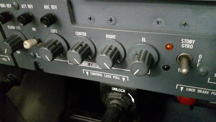
What we had was somewhat strange. With the door hanging open and the handle down, we had a green indication...... not right. We did have a normal green for the door closed and handle up. We could only get a amber with the door open and the handle up. Normal amber comes from "either" the door open or handle down.

We also had Flight Warning Computer "Fwd Cargo Door Switch" faults.


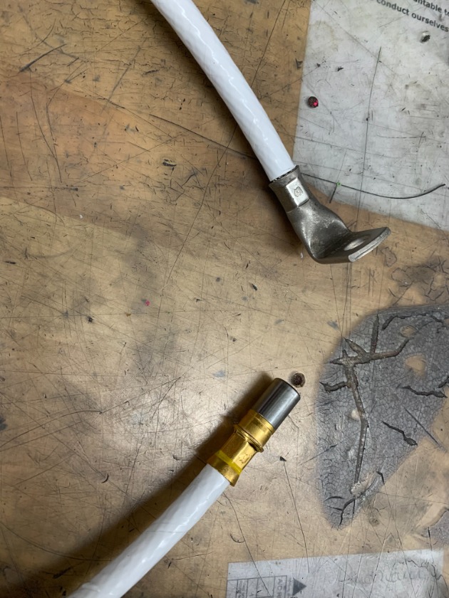
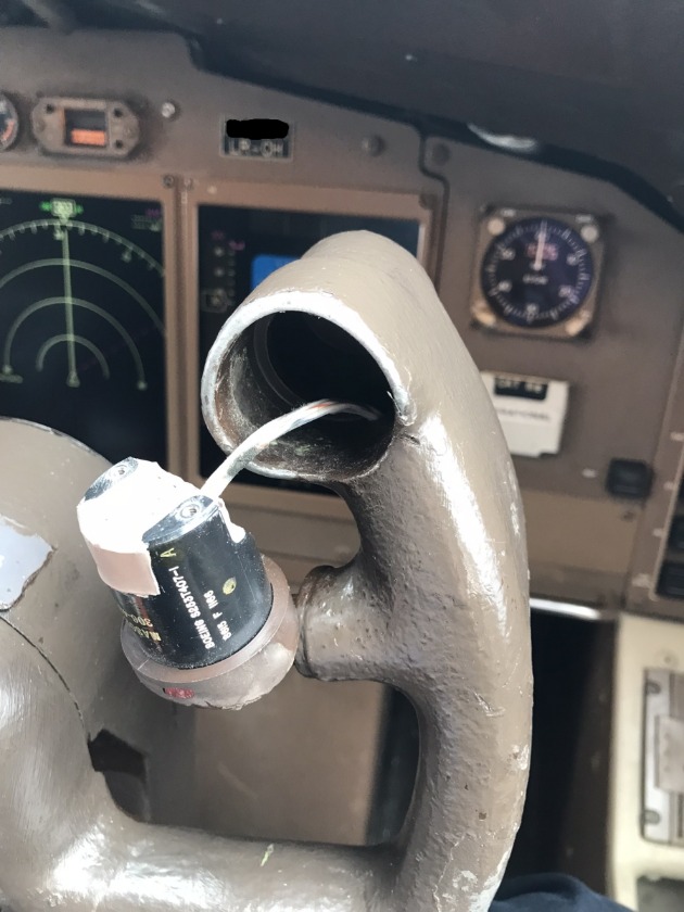
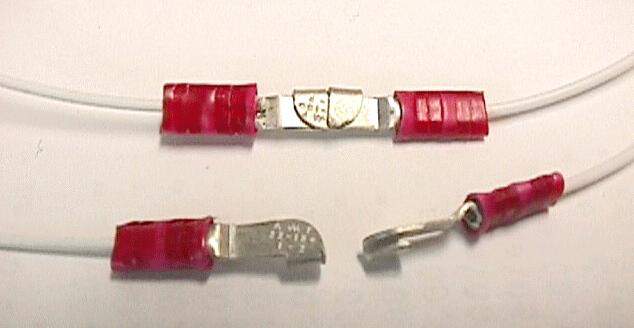
(Crappy picture.... sorry)

We went for the most likely problem area first. With the door open, we cut the wrapping off the frame-to-door harness. One busted wire and one right on the edge. We fixed them both.


Problem repaired???? Hell no. We probably broke the wire opening up the harness, but repairing them "should" prevent future breaks. At least for a while.

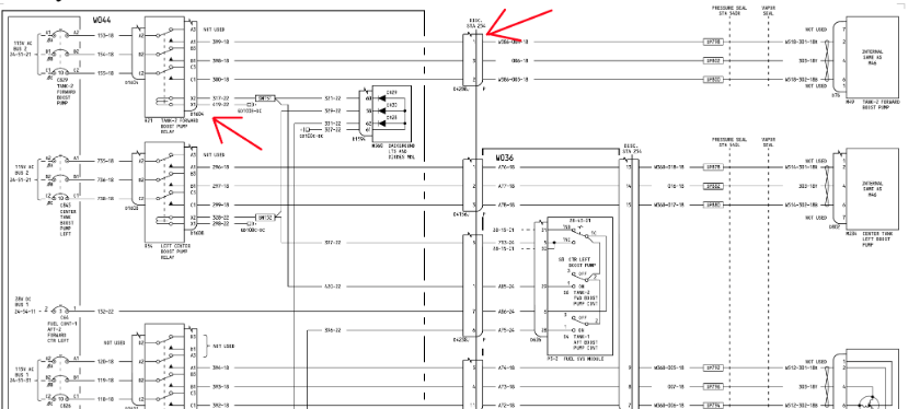
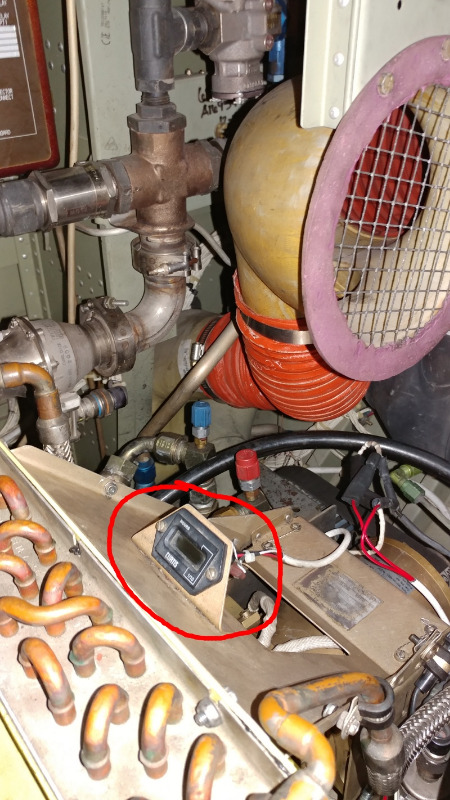
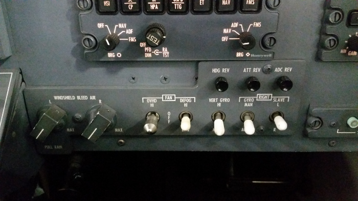
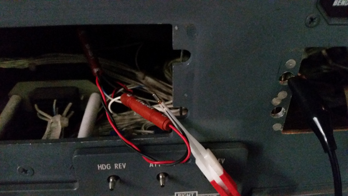
Time to open some crap up and grab a meter. We took the forward right ceiling off to gain access to terminal block 4004VT


As a precursor, both the #1 FWC and the SDAC were seeing the fault. The FWC receives all three grounds for its circuitry, but the SDAC only looks at one. If both computers were seeing a problem, it was most likely on the one wire that fed them both.

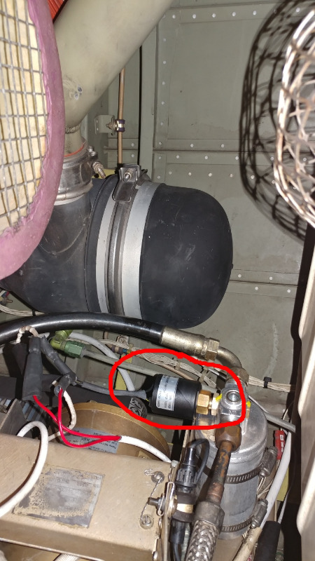
Two FWC's, blue on top - SDAC, single black box below.


These are just grounds we're looking for, but the meter was all over the place. Good continuity, 7K ohms, 14M ohms. Shut the handle, shit changes. Make the door switch, more weird readings. OK... off come the door panels to get to terminal block 4002VT.

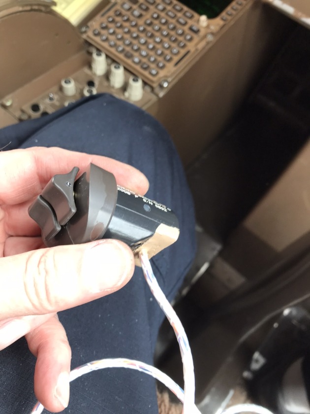
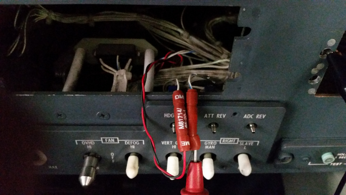
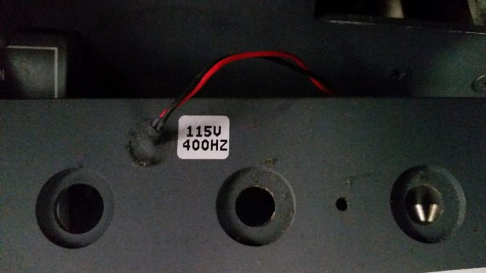
To eliminate door harness wiring I made a jumper.


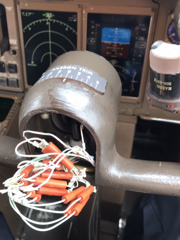
No help. Finally... after three hours of dicking with this thing, I decided to remove the two suspect wires from pins "B" and "G" of block 1 on 4002VT. I used a jumper to hook them together........ The problem went away!!!!


Solution.... replace a shorted out terminal block. The two pins in question were shorted out to one or more of the adjacent pins. Thus the screwed up meter readings. The door has no insulation in this area, so that terminal block has been frozen a thousand times over. It finally gave out.

I'll keep this fix in the memory bank for a while.


A300-600 ASM 52-71-00
AWM 52-71-02
Displaying 1 - 14 out of 14 results.
Time to create page: 0.960 seconds