We had another problem similar to
this
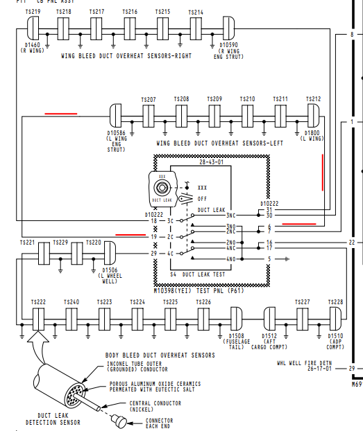
one dealing with the left bleed air system. In the case of this particular aircraft, the overheat switches were part of a different warning system so we were dealing with just the loops.
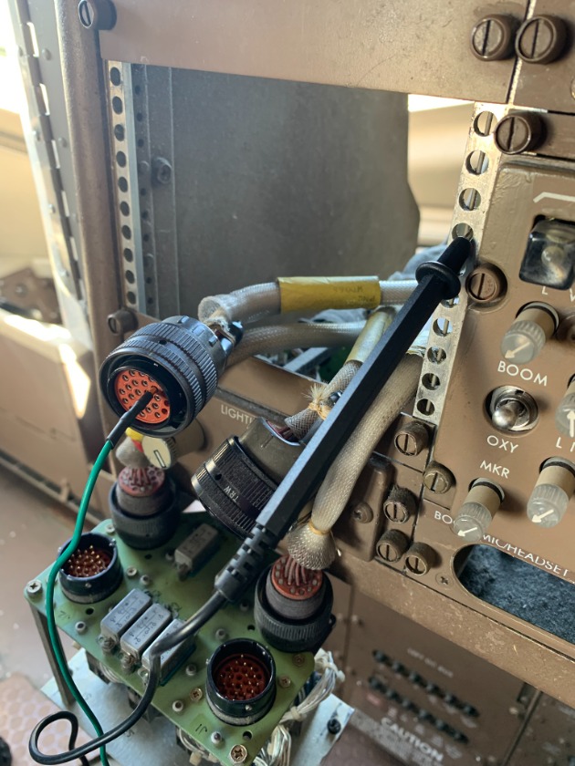
As with either type of configuration, everything can be checked from the system test panel. Both ends of each loop.... (left, right, and body) converge at the plugs behind the panel.
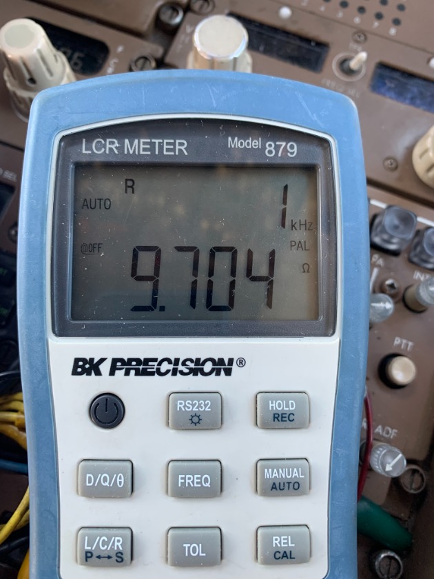
The reading from end-to-end of the loop in question was around 9Ω, which is a good reading.
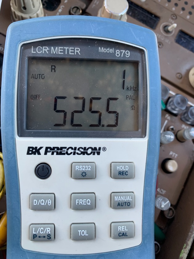
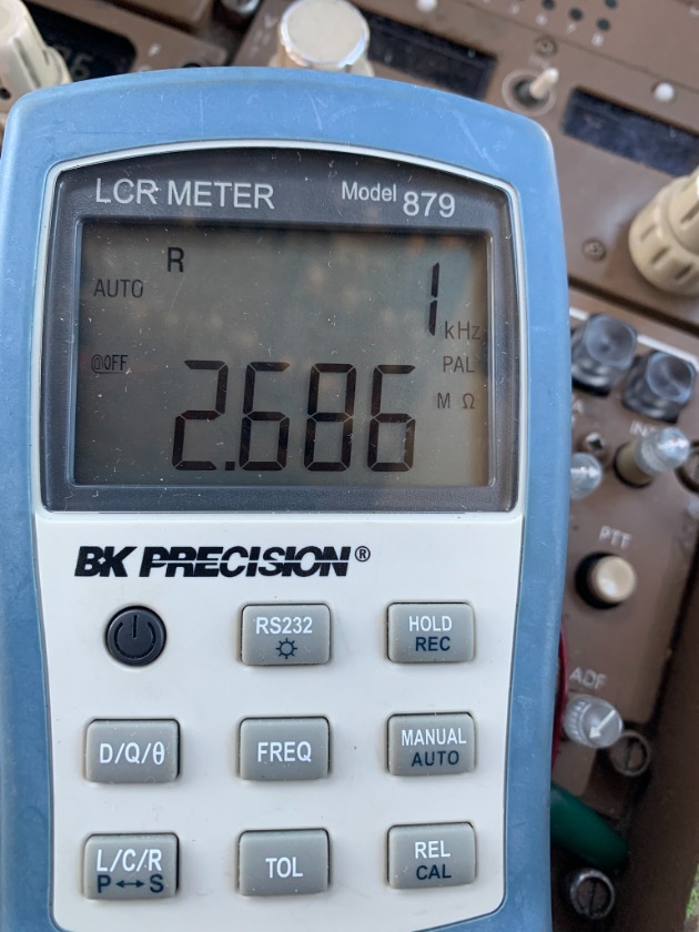
A problem was noted when a short to ground was checked. Just over 500Ω while a known good system was 2.4MΩ+.
500Ω does sound like a pretty high resistance, but we're dealing with a static aircraft with no wing fluctuations from flight.
Now comes the "fun" part. If both ends of the loop show a short to ground, how do you trace it down?
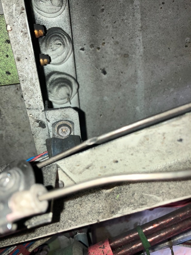
You try to find an accessible point halfway in the loop series and disconnect the junction. The short will now only be on one pin. That takes you either outboard or inboard. Ours was outboard. When the next junction was separated..... the short went away. Meaning, the loop between the first disconnect and the second was bad.
A bracket arm had broken free of its mount and had rubbed into the loop.
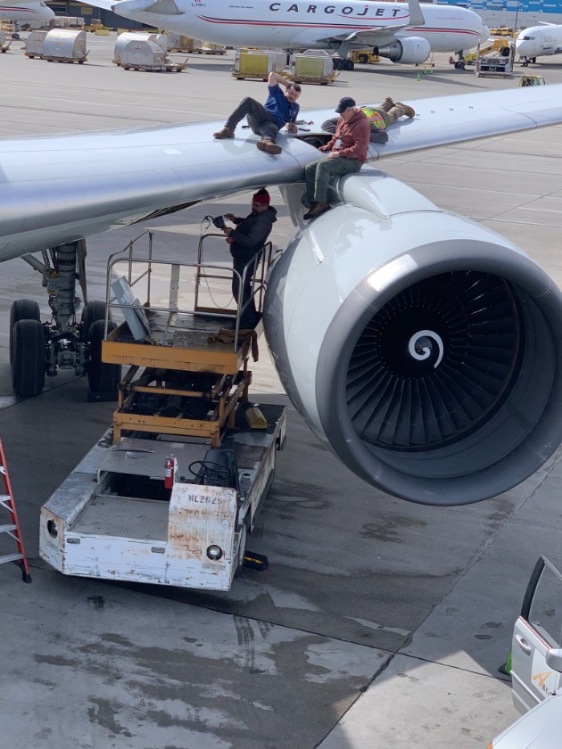
Gaining access to these connections can be quite difficult. The more "hands on deck" the better.....