| Suppression Diode |
||
|
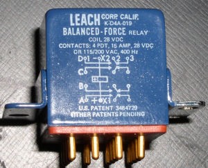
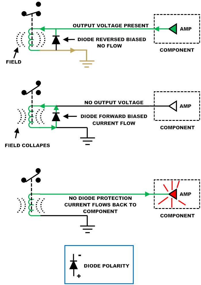
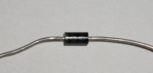
The majority of relays installed on aircraft will have a diode installed in parallel with the relay coil. This diode is often referred to as a "Suppression Diode". The diode can be installed internal as part of the relay assembly or external as a standalone component. The purpose of the diode is for circuit protection.
All inductors (relay coils included) will build up an electrical field around themselves when voltage is present. If the voltage is removed the field will collapse. As the field collapses a current is induced in the wiring connected to the coil. The suppression diode gives a path for this current to dissipate.
The suppression diode must be accounted for when continuity checking a circuit that has a relay coil in it. It is very possible to read through just the diode when the relay coil is open. Isolation of the diode might be needed for verification of a good circuit.
|
 |
|
 |
||
 |
||
|
THE INFORMATION PRESENTED ON THIS SITE IS TO BE USED AS A GUIDE. APPROVED AIRCRAFT MANUFACTURER MAINTENANCE MANUAL PROCEDURES SHOULD ALWAYS BE FOLLOWED. |
||
| 429 Data Bus |
||
|
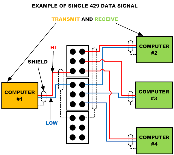
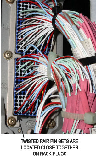
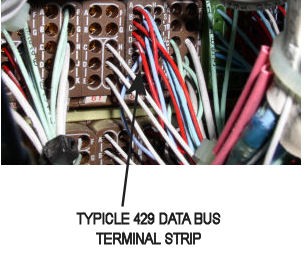
The ARINC® 429 Data Bus is a standard used for digital information transfer between computers. Data is transmitted in ONE direction only. The output of one computer can feed several other computers, but the receiving computers cannot return information on the same set of wires. Every major avionics computer that uses 429 for communications will have numerous transmitting and receiving circuits. Each circuit uses a 24 gauge twisted pair wire set for data transfer. Having separate wires for each circuit usually means there are literally hundreds of twisted pair wire sets running between components. (A new standard “629” is a bi-directional system that greatly reduces wire runs and weight.)
429 Data Bus information is composed of “Labels” of information. As an example: a typical digital Air Data Computer will output labels 210 - True Airspeed, 215 - Impact Pressure, 242 - Total Pressure, plus more than 30 other labels related to the aircraft flight environment. These outputs are continuously updated several times a second. They are fed to all the computers or components that require this information. Air Data information is used by the FCC, FMS, and Auto/Throttle computers. Other systems such as pressurization, ground proximity, and engine controls also require digital air data inputs. Flight information to the flight crews is displayed on the EFIS from the symbol generators. The SG’s receive 429 data from the Air Data System.
429 Data Bus systems have proven to be extremely reliable. When a failure does occur, troubleshooting and repair can range from a simple box replacement to a total nightmare. Built in Test Equipment (BITE) is usually the first avenue for verifying problems. Normally, any hiccup of digital data is recorded. BITE systems are a great tool for problem isolation. Major headaches can usually be expected when the BITE system doesn’t work.
|
|
|
|
|
||
 |
||
 |
||
|
THE INFORMATION PRESENTED ON THIS SITE IS TO BE USED AS A GUIDE. APPROVED AIRCRAFT MANUFACTURER MAINTENANCE MANUAL PROCEDURES SHOULD ALWAYS BE FOLLOWED. |
||
| Transformer Troubleshooting |
||
|
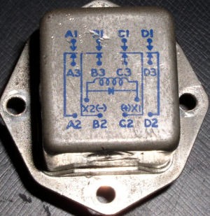
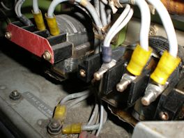
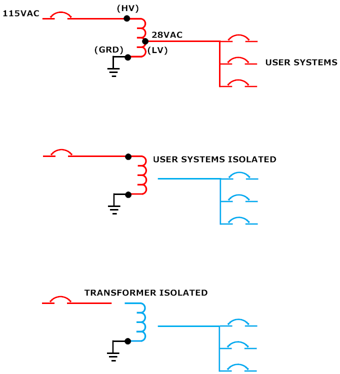
Many circuits on aircraft use step down transformers for control voltages. Typical user systems are lights and 28VAC position synchros.
Troubleshooting a short that is causing a breaker trip is a fairly simple task. Isolating the user systems by disconnecting the LV connection is the first step. If the control breaker remains in, the short is "downstream" from the transformer. If the breaker is still popping, the HV line should be disconnected to isolate the transformer itself. If the breaker stays in, the transformer is shorted. |
 |
|
 |
||
|
THE INFORMATION PRESENTED ON THIS SITE IS TO BE USED AS A GUIDE. APPROVED AIRCRAFT MANUFACTURER MAINTENANCE MANUAL PROCEDURES SHOULD ALWAYS BE FOLLOWED. |
||