Rotate Aero
  • Home
  • Forum
  • Blog
  • Community
  • Contact
  • Search the Site

   
Terminals & Splices 


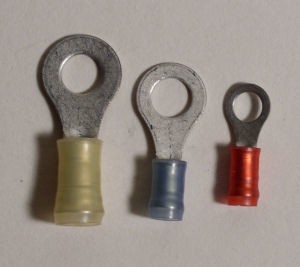
Wire repair often requires the use of terminals and splices. The proper crimping procedures and instructions for tool use are covered in the aircraft Wiring Practices Manual. Terminals are used extensively for aircraft frame (ground) connections and terminal strip interconnects. Splices are normally used for wire repair. The use of "exposed" splices is limited to areas inside the pressure vessel with no chances of chemical (Skydrol®) contamination.


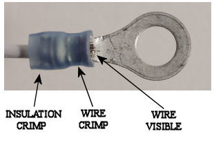
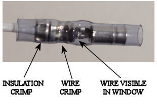
All terminals and splices are designed for double crimps. The crimp on the wire insulation provides tensile strength. The crimp on the wire itself is for electrical conductivity. To long or short of a wire strip will decrease the effectiveness of the connection.


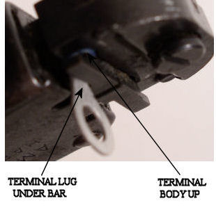
Proper placement in the crimping tool is also needed. A terminal or splice that has not been positioned correctly will most likely be bent out of shape. Crimping tool damage could also result. Once the first "click" is heard while crimping, the tool must finish the cycle before the crimp head will open.


ts3


 ts1
 ts2
 ts4  ts5
ts7 ts8


Quick Notes for Crimping


  1. Color codes for wire gauge are standard for all aircraft usage. Yellow 10-12, Blue 14-16, and Pink/Red 18-22.
  2. The inserts shown with the splices on this page allow for two different wire gauges to be connected together. The blue insert fits into a yellow splice and the red insert fits into a blue splice.
  3. The tool, terminals, and splices shown here are commonly used on aircraft manufactured in the United States. Airbus® aircraft have a slightly different style and material for their terminals. A specific tool is needed for crimping these, but a double crimp is still the result.
  4. Crimping tools will have an alignment bar for placement. Splices will have a notch that fits under this bar. Terminal lugs also go under this bar. If the terminal is positioned correctly, the bar acts as a "stop" for the wire as it is inserted.
  5. A good splice is characterized by the two crimps at the correct locations and wire visible through the inspection window at the midpoint of the splice.
  6. A good terminal connection will have two properly placed crimps along with the wire visible on the lug side of the terminal.
  7. Automotive crimpers and channel lock pliers are not proper for aircraft terminal or splice usage.


THE INFORMATION PRESENTED ON THIS SITE IS TO BE USED AS A GUIDE.

APPROVED AIRCRAFT MANUFACTURER MAINTENANCE MANUAL PROCEDURES SHOULD ALWAYS BE FOLLOWED.


Environmental Splices 


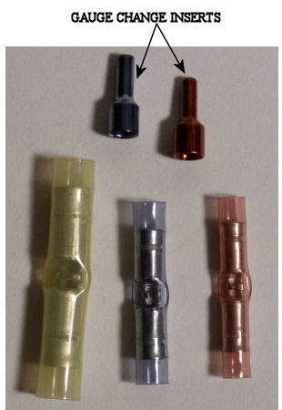
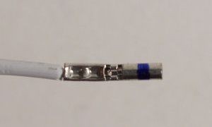
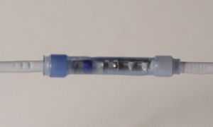
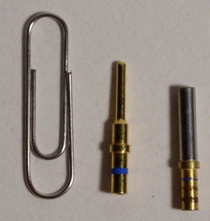
Environmental Splices should be used anytime a splice is needed outside the pressure vessel. This type of splice should also be used if there is any chance of liquid exposure.


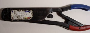
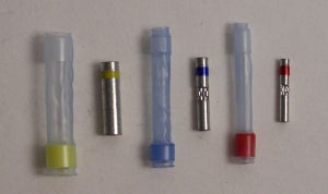
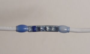
The splice is composed of two parts, the inner barrel, and the outer sleeve. The barrel provides a solid wire to wire connection. The sleeve has sealant on both ends. When heated, the sealant flows around the wire and the sleeve body shrinks. The splice completely isolates external elements to greatly reduce the chance of failure over time. Environmental splices are manufactured by Raychem®, they require the correct crimper be used.

 ray1
 ray2
 ray3  ray4


ray5


Ray6


Quick Notes for Environmental Splices


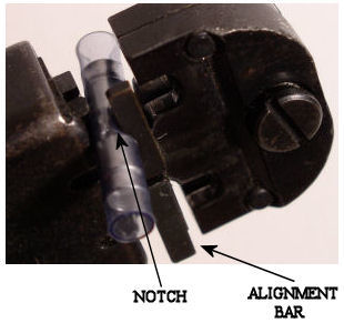
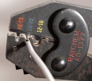
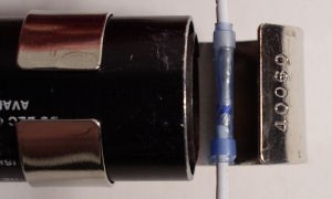
The AD-1377 crimper is used for barrel crimping. It places a double crimp on each side of the barrel.


  1. The crimp depth is important. The tool might need adjustment; the barrel as a tendency to bend along the length if the crimp is too tight.
  2. The placement of the color stripes on the barrel and sleeve are used for a reference only. It does not matter if they are matched.
  3. A good heat gun is needed. Having a curved tip adapter is also helpful. A considerable amount of heat is needed to allow for sealant flow. Portable heat guns normally do not have enough heat or flow. Butane torches will burn through the sleeve before sealant flow, they are not recommended.
  4. A good splice is characterized by two solid crimps on each wire and complete sleeve shrink with sealant flow on both sides.


THE INFORMATION PRESENTED ON THIS SITE IS TO BE USED AS A GUIDE.

APPROVED AIRCRAFT MANUFACTURER MAINTENANCE MANUAL PROCEDURES SHOULD ALWAYS BE FOLLOWED.


Front Release Plugs 


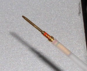
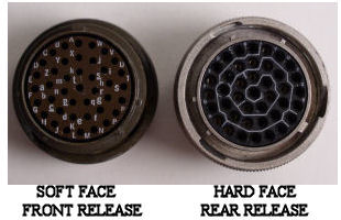
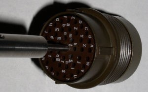
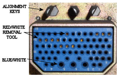
Front release plugs are found on older analog based aircraft. Newer generation applications use rear release plugs for most applications. Both types of plugs use locking tabs around each pin. The tabs must be spread open for the pin to be removed.


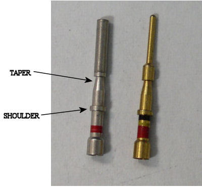
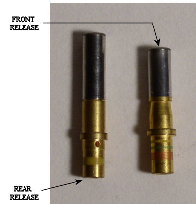
A quick visual of the front face is all that is needed to differentiate between the two. Front release will have rubber on the face and rear release will have a hard plastic material. Front release pins have a noticeable taper in diameter that starts after the shoulder.


The standard ranges of pin sizes are red, blue, and yellow. Red pins for gauges 18-22 receive the majority of use.


The most common purpose is for signal wires. The larger blue and yellow pins are found for power functions. It is not uncommon to find intermixing of pin sizes in the same plug.


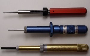
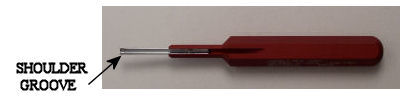
Front release plugs use a pin pusher tool to remove the pins from front to back. The tools are made by several manufactures, but they all work in the same fashion.


front4


 front1
front2
 front3  front5


Quick Notes on Front Release Plugs


  1. Selection of the proper tool color is an easy task. The pin diameter will dictate which color to use. The possibility of a mistake is slim. When the tool is placed around the pin the fit should be snug.
  2. The tool should be inserted and fully seated around the pin. A definite stop will be felt. Pin push tools can be rotated left/right to assure a full seat is made. If the tool has not been placed properly, the locking tabs will not be expanded and the pin cannot be removed.
  3. Pin extraction is completed by pushing the plunger. If the pin has a wire, a moderate pull will help to remove it fully from the plug. If no wire is present, a stick pin or paper clip from the plug front will help complete the extraction. Grabbing the base of the pin with needle nose pliers from the plug back is not recommended. If the base is deformed, it will call for rejection of the pin.
  4. A pin is placed into the plug with an insertion tool. The tool will have a groove at the end that is designed to fit around the pin base. A small click will be felt when the pin is seated and the locking tabs engage. If the wire gauge permits, I will use the wire alone for insertion.


Plug Numbering and Replacement


  1. All plugs that use letters for pin identification do not use "I" , "O", or "Q".
  2. Plugs that use numbers for identification will have parentheses "( )" around every tenth digit.
  3. Plug replacement requires extreme care. Any mismatch of pins can be cause for headaches when trying to verify the mistakes. I do not follow the letters or numbers around the plug. Most plugs will have the pins aligned in rows. It is much easier to start at one edge and do one row at a time. This prevents problems near the end of the plug change, trying to stab pins into the middle with wires all around. Each pin needs to be double, and then triple checked before moving on to the next one.
  4. Placing pins in the unused positions will help the "next guy down the line". If a pin is needed but not available in the shop, a spare can be used from the plug itself.


THE INFORMATION PRESENTED ON THIS SITE IS TO BE USED AS A GUIDE

APPROVED AIRCRAFT MANUFACTURER MAINTENANCE MANUAL PROCEDURES SHOULD ALWAYS BE FOLLOWED.


Rear Release Plugs 


Rear release plugs are found on newer generation digital aircraft. They have proven to be reliable against moisture and chemicals. The face of the plug will be a hard plastic material as compared to rubber on front release plugs. Both types of plugs use locking tabs around each pin. The tabs must be spread open for the pin to be removed. Rear release pins do not have a taper. Locking tabs engage the shoulder to keep the pin in place.


The standard ranges of pin sizes are red, blue, and yellow. Red pins for gauges 18-22 receive the majority of use. The most common purpose is for signal wires. The larger blue and yellow pins are found for power functions. It is not uncommon to find intermixing of pin sizes in the same plug.


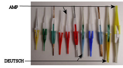
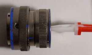
Plastic or metal insertion/extraction tools are required to work on rear release pins. The tools are made by Amp® and Deutsch®. Both manufacture's plugs are used extensively throughout aircraft avionics/electrical systems.


rear2

   rear1
   rear3
   rear4


Quick Notes on Rear Release Plugs


  1. All removal/insertion tools are color coded for pin size. The white side is used for removal. The colored side is for insertion. Deutsch tools are cylindrical at the midpoint. Amp's have a square shape.
  2. One major hassle with removal tools is placing the wire “in the tool”. If the wire length is available, it can be “walked in” from the gap further back on the tool body.
  3. A considerable amount of skill is needed to remove pins from some rear release plugs. The main problem is seating the tool fully around the pin shoulder. As with front release, if the tool is not fully seated the tabs will not release and the pin cannot be removed.
  4. There are many occurrences in which one type of tool works better than the other. If an Amp tool doesn’t seem to work, better luck may be found with a Deutsch.
  5. The majority of the time the tool will stop at the pin base. It can be tilted along the length to help get over the base. A good seat can be "felt" with your fingertips.
  6. Plastic extraction tools cannot be rotated left/right after placement in plug. If a good seat is not made, remove the tool and reposition before inserting again. If a tool is rotated, it will break. If any pieces are left in the plug that cannot be removed, the whole plug will need to be rejected. Any stray plastic pieces will prevent a tool from seating and the tabs will remain engaged.
  7. I will use the metal tools as a last resort. The metal tools shown here along with the tweezers type can easily damage the locking tabs if they are not used properly.
  8. Female pins without wires can be assisted out of the plug with a paper clip or stick pin from the front side. The push rod from a front removal tool is helpful with male pin removal. The rod tip is concave, it can push the pin up enough to grab the base from the backside (fingers only, do not use pliers).
  9. Rear release plugs usually have little resistance to pin insertion. If a pin has a wire attached, the wire is normally all that is needed for insertion. A click will be felt when the tabs engage. A slight tug on the wire will verify the pin is locked. Blank pins need the tool to be inserted.


Plug Numbering and Replacement


  1. All plugs that use letters for pin identification do not use “I”, “O”, or "Q".
  2. Plugs that use numbers for identification will have parentheses “( )” around every tenth digit.
  3. Plug replacement requires extreme care. Any mismatch of pins can be cause for headaches when trying to verify the mistakes. I do not follow the letters or numbers around the plug. Most plugs will have the pins aligned in rows. It is much easier to start at one edge and do one row at a time. This prevents problems near the end of the plug change, trying to stab pins into the middle with wires all around. Each pin needs to be double, and then triple checked before moving on to the next one.
  4. Placing pins in the unused positions will help the “next guy down the line”. If a pin is needed but not available in the shop, a spare can be used from the plug itself.
     

THE INFORMATION PRESENTED ON THIS SITE IS TO BE USED AS A GUIDE.

APPROVED AIRCRAFT MANUFACTURER MAINTENANCE MANUAL PROCEDURES SHOULD ALWAYS BE FOLLOWED.


Rack Plugs


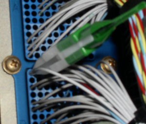
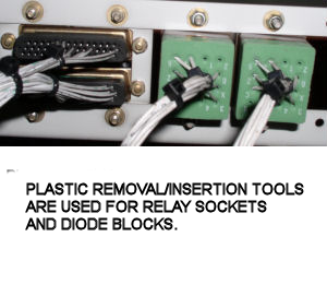
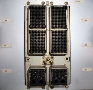
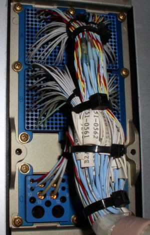
Rack plugs are used for LRU interface. There are many types and sizes for component connections. Rack plugs are similar to rear release plugs, all pins are released and removed from the back of the plug.


Rack plugs use locking tabs for pin retention. The plastic removal/insertion tools can be used in the majority of applications for pin removal. Both sides (front/rear) of the plug are constructed with hard plastic. There is normally very little resistance to tool insertion and the pins are easily released.


rack3


rack4


 rack1
 rack2
rack5

 blocks1


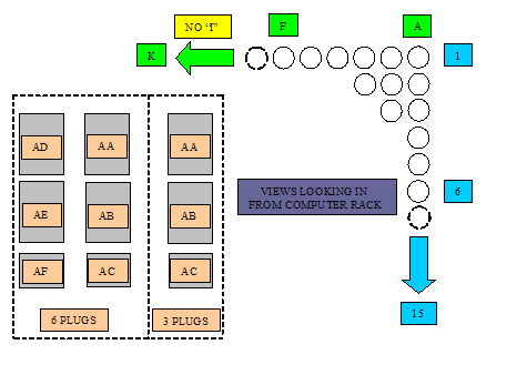
Quick Notes on Rack Plugs


  1. The most common difficulty with rack plugs is getting a clear view and straight shot at the back of the plug. Some radio racks require extensive dismantling for plug access.
  2. Identifying and removing pins is also hampered by the wiring going to the plug. A large wire bundle will require to be "opened up" to gain access to the plug's inner pins.
  3. All removal/insertion tools are color coded for pin size. The white side is used for removal. The colored side is for insertion. Deutsch® tools are cylindrical at the midpoint. Amp® tools have a square shape.
  4. One major hassle with removal tools is placing the wire "in the tool". If the wire length is available, it can be "walked in" from the gap further back on the tool body.
  5. There are many occurrences in which one type of tool works better than the other. If an Amp tool doesn’t seem to work, better luck may be found with a Deutsch. I have found the Amp tools work very well for most plugs.
  6. Rack plugs usually have little resistance to pin insertion. If a pin has a wire attached, the wire is normally all that is needed for insertion. A click will be felt when the tabs engage. A slight tug on the wire will verify the pin is locked. Blank pins need the tool to be inserted.


Computer Racks


  1. Computer racks have two, four, or six high density plugs. It is common to find numerous signal wire pairs in these plugs. Signal wires are twisted pair/trip with a shield. The wires are red/blue or red/blue/yellow.
  2. Careful attention needs to be placed on pin identification. Each plug has 150 pins; it is very easy to access the wrong pin.
  3. The AMP® green/white plastic tool works well on these plugs.
  4. The pins are male. When fully inserted in the plug, each pin is enclosed in a cylindrical socket. The computer has female pins that fit around the male and into the socket. Safety wire should not be used as a makeshift test lead on these pins. If a pin is not in alignment, it will be shoved back, breaking the locking tabs when the computer is placed in the rack.


rack7
   

THE INFORMATION PRESENTED ON THIS SITE IS TO BE USED AS A GUIDE.

APPROVED AIRCRAFT MANUFACTURER MAINTENANCE MANUAL PROCEDURES SHOULD ALWAYS BE FOLLOWED.

     
  1. Terminal Strips

Rotate Aero Users

  • dynamics
  • diego1
  • Epopour
  • Clipper
  • rabin
  • Lintotomy09
  • OG GarlicSalt
  • peter.waters01
  • Brooks
  • Jz777
  • bravoguy
  • minhas1
  • Sana Jackson
  • Lim, Hyeong-Jang
  • john.sanders

Random acts of kindness are contagious!!

Don't have an account?
Register now to join the community!
© 2023 Rotate.Aero
  • Thor's Hammer
  • Sitemap
Login
  • Register for an account
  • I forgot my username
  • I forgot my password