| Resistance |
||
| Checking wire continuity or component resistance is a simple task. The majority of avionics/electrical troubleshooting requires the ability to decipher meter readings correctly. | ||
|
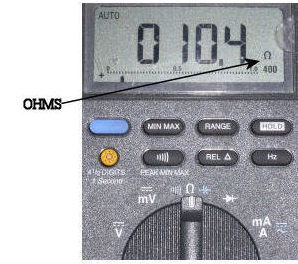
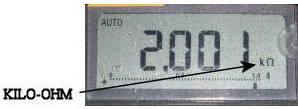
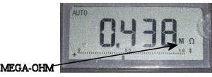
Particular attention to the Ω symbol when shooting electrical components is needed. The biggest mistake while using a meter is not observing the Ω, KΩ, MΩ indication. The display of .562 does not always represent ½ ohm, although I have noted this mistake many times. More than likely the meter is indicating .562KΩ or .562MΩ which is significantly higher than ½ ohm. The two readings above are 562 ohms and 562 thousand ohms, respectively.
Continuity checking a wire from the tail area to the E/E compartment of a 747 for example, can read numerous indications depending on wire condition. I tend not to get to excited about 25Ω or less. This would be a long run compared to most aircraft. The most common problem I have experienced while shooting a wire using ground as a reference, is the ground itself. Using a poor ground connection on either end can give a bad indication for a wire that is likely good.
I tend not to use the buzzer function of the meter for wire checking as verification of a good wire. Direct observation of the meter reading is recommended. |
 |
|
 |
||
 |
||
|
Helpful Tips for Component Resistance Readings
Closed relay contacts and plug contacts should be as close to 0Ω as possible. Other components such as solenoids and sensors will have higher readings. Many of the correct values for such components can be found in maintenance or troubleshooting manuals. Most parts are duplicated on aircraft. Sometimes comparison to a known good component is helpful.
|
||
|
THE INFORMATION PRESENTED ON THIS SITE IS TO BE USED AS A GUIDE. APPROVED AIRCRAFT MANUFACTURER MAINTENANCE MANUAL PROCEDURES SHOULD ALWAYS BE FOLLOWED. |
||
Rotate Aero Users
Random acts of kindness are contagious!!
Don't have an account?
Register now to join the community!
©
2026
Rotate.Aero