
- Posts: 321
- Thank you received: 0
Ground Fault Interruper
2 years 1 month ago #914
by dynamics
Ground Fault Interruper was created by dynamics
Mark, regarding to engine feed boost pump wiring diagram I' ve emailed attached, would you mind explain why there is not any comparator circuit (to detect ground leakage from comparing the amount of current going and returning) for relays R20&R55 which act as ground fault interrupter (GFI)?
Please Log in or Create an account to join the conversation.
2 years 1 month ago #915
by dynamics
Replied by dynamics on topic Ground Fault Interruper
I sent the wiring diagram file just a moment ago.....
Please Log in or Create an account to join the conversation.

2 years 1 month ago #916
by Mark
Replied by Mark on topic Ground Fault Interruper
The relays mentioned do not act as a GFI. The way they are drawn it looks like they might have that function, but they don't.
The diode in the relay itself is a suppression diode as explained here .
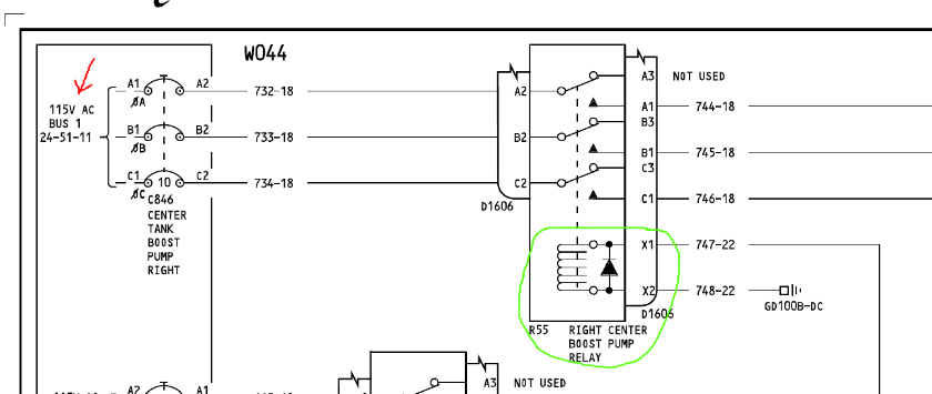
Actual current protection occurs further upstream from the 3-phase breaker for the pump.
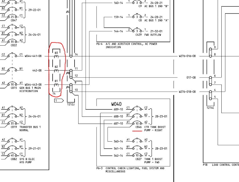
In this case, CT (T4) is the load side sensing device for the whole "Gen Bus 1 Main Distribution" power bus. There will be another current transformer on the feed side (usually close to the generator output) that the Bus Protection Unit compares amperage loads.
A explanation of a actual load differential can be found here .
If the Bus Protection Unit senses a amperage difference on any leg of a 3-phase circuit it disconnects the power source from the load. This can be an open leg in which one phase is carrying no load or a shorted leg which is carrying a massive load compared to the other two.
The diode in the relay itself is a suppression diode as explained here .
Actual current protection occurs further upstream from the 3-phase breaker for the pump.
In this case, CT (T4) is the load side sensing device for the whole "Gen Bus 1 Main Distribution" power bus. There will be another current transformer on the feed side (usually close to the generator output) that the Bus Protection Unit compares amperage loads.
A explanation of a actual load differential can be found here .
If the Bus Protection Unit senses a amperage difference on any leg of a 3-phase circuit it disconnects the power source from the load. This can be an open leg in which one phase is carrying no load or a shorted leg which is carrying a massive load compared to the other two.
Please Log in or Create an account to join the conversation.
2 years 1 month ago #917
by Mark
Replied by Mark on topic Ground Fault Interruper
The circuit breaker C846 should pop open if one leg of the pump power goes short to ground.
Fuel pumps "can" run on two phases, but they get hot. Some pumps have a thermal switch which kills power to the pump itself.
I do not know the current difference that the Bus Control Unit uses as limits for a disconnect. This fuel pump breaker is 10 amps. I would guess the disconnect threshold is higher which is why I think the breaker is the main source of protection for a fuel pump.
Please Log in or Create an account to join the conversation.
2 years 1 month ago - 2 years 1 month ago #940
by Mark
Replied by Mark on topic Ground Fault Interruper
Another explanation of differential protection
here
.
Last edit: 2 years 1 month ago by Mark.
Please Log in or Create an account to join the conversation.
2 years 1 month ago #941
by dynamics
Replied by dynamics on topic Ground Fault Interruper
Mark, I believe the airframe structure acts as a neutral wire for three phase supply wires of pump, so that the leakage current from faulted phase return to the generator through the structure and ground wire of the generator, please correct me if I am wrong
Please Log in or Create an account to join the conversation.
2 years 1 month ago - 2 years 1 month ago #942
by Mark
Replied by Mark on topic Ground Fault Interruper
I'm confused about your term "leakage". I'm going to assume you mean short to ground.
You're getting into basic electronic theory.
A short to ground, whether it's AC or DC, will cause a much higher flow of electrons through a wire. I guess technically, the electrons are going back to the generator via the airframe, but that really isn't the point.
Aircraft CT (Current Transformer) systems don't care what path the electrons travel. They only care about the current going through the wires at their measuring point.
A short would cause to much current flow in one or two wires (all three at times). An open circuit would cause minimal to zero current flow. The CT wants to see "0" current flow between the three wires combined. That's all it cares about.
There are really two electical power protection systems on an aircfaft, a CT will either trip power to the whole system or a circuit breaker will pop. Either one stops current flow.
Back to electron flow..... if electrons move from negative to positive, wouldn't that mean that they are coming "from" the airframe and not "to" the airframe? We don't think of current flow as such. We think in terms of "going to ground". Backward..... yes, but it's best to stick with conventional thinking. It's much less confusing.
Last edit: 2 years 1 month ago by Mark.
Please Log in or Create an account to join the conversation.
2 years 1 month ago #943
by dynamics
Replied by dynamics on topic Ground Fault Interruper
Mark, the ground fault scenarios for AC and DC circuit are very different, and the problem is that it doesn't necessarily lead to very high current that may be detectable by CB or CT! I want to draw your attention to AC circuit, in which while there is no fault the circuit is balanced so that sum of phasors (phasor is mathematical representation of each phase current) is zero, and there is no electric current through neutral wire i.e. airframe structure, But if there is a phase to phase ground fault,the circuit would no longer be balanced so that sum of phasors would be non zero and there is electric current through the neutral wire i.e. airframe structure. such a ground fault current would be in the form of electrons leap from the faulted phase to the airframe. The problem is that even very low leap energy as low as 200 microjoules that is still a safety issue as it would lay foundation for initiation of ignition in the fuel tank, is not a hard short that would trip the circuit breaker! I am not sure CT would detect such low energy electrical drain! so a sort of fast acting circuit protective devices such as ground fault Interrupter is necessary that trip the supply power once non zero sum of phasors is detected.
Please Log in or Create an account to join the conversation.
2 years 1 month ago - 2 years 1 month ago #944
by Mark
Replied by Mark on topic Ground Fault Interruper
You keep saying Ground Fault Interrupter and I keep saying CT. There "are" a few aircraft that I have worked on that actually have a center fuel tank pump GFI. I don't have an image now, but if I get a chance..... I'll post a picture.
The GFI acts in the same manner as a CT. It's looking at current flow. Anything out of the ordinary, it'll trip power.
The whole point of fuel pump wiring is it is external of the tank. The only wires "in" the tank are fuel quantity and fuel level sensors. The voltages feeding either is extremely low.
Shorts and opens in fuel pump wiring do occur (I've seen plenty), but these are not a threat to the fuel in the tank. That's the whole point of having the pump motor external and the pump impeller internal. These sections of the pump are separated by o-rings (or seals) that keep the fuel in and the electrons out.
The problem is that even very low leap energy as low as 200 microjoules that is still a safety issue as it would lay foundation for initiation of ignition in the fuel tank.....
Again, the wires are external. I don't know where to go on with this??? I have never heard of fuel pump wiring causing tank fires.
Last edit: 2 years 1 month ago by Mark.
Please Log in or Create an account to join the conversation.
Time to create page: 0.832 seconds
Don't have an account?
Register now to join the community!
©
2025
Rotate.Aero