Rack Plugs


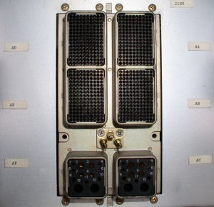
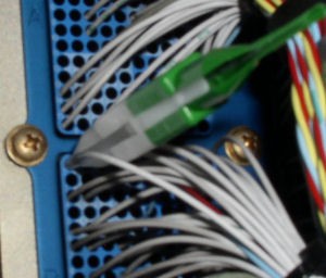
Rack plugs are used for LRU interface. There are many types and sizes for component connections. Rack plugs are similar to rear release plugs, all pins are released and removed from the back of the plug.


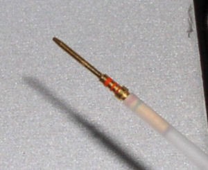
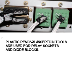
Rack plugs use locking tabs for pin retention. The plastic removal/insertion tools can be used in the majority of applications for pin removal. Both sides (front/rear) of the plug are constructed with hard plastic. There is normally very little resistance to tool insertion and the pins are easily released.


rack3


rack4


 rack1
 rack2
rack5

 blocks1


Quick Notes on Rack Plugs


  1. The most common difficulty with rack plugs is getting a clear view and straight shot at the back of the plug. Some radio racks require extensive dismantling for plug access.
  2. Identifying and removing pins is also hampered by the wiring going to the plug. A large wire bundle will require to be "opened up" to gain access to the plug's inner pins.
  3. All removal/insertion tools are color coded for pin size. The white side is used for removal. The colored side is for insertion. Deutsch® tools are cylindrical at the midpoint. Amp® tools have a square shape.
  4. One major hassle with removal tools is placing the wire "in the tool". If the wire length is available, it can be "walked in" from the gap further back on the tool body.
  5. There are many occurrences in which one type of tool works better than the other. If an Amp tool doesn’t seem to work, better luck may be found with a Deutsch. I have found the Amp tools work very well for most plugs.
  6. Rack plugs usually have little resistance to pin insertion. If a pin has a wire attached, the wire is normally all that is needed for insertion. A click will be felt when the tabs engage. A slight tug on the wire will verify the pin is locked. Blank pins need the tool to be inserted.


Computer Racks


  1. Computer racks have two, four, or six high density plugs. It is common to find numerous signal wire pairs in these plugs. Signal wires are twisted pair/trip with a shield. The wires are red/blue or red/blue/yellow.
  2. Careful attention needs to be placed on pin identification. Each plug has 150 pins; it is very easy to access the wrong pin.
  3. The AMP® green/white plastic tool works well on these plugs.
  4. The pins are male. When fully inserted in the plug, each pin is enclosed in a cylindrical socket. The computer has female pins that fit around the male and into the socket. Safety wire should not be used as a makeshift test lead on these pins. If a pin is not in alignment, it will be shoved back, breaking the locking tabs when the computer is placed in the rack.


rack7
   

THE INFORMATION PRESENTED ON THIS SITE IS TO BE USED AS A GUIDE.

APPROVED AIRCRAFT MANUFACTURER MAINTENANCE MANUAL PROCEDURES SHOULD ALWAYS BE FOLLOWED.