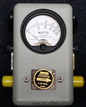
The Watt Meter is used to verify the operational integrity of VHF and HF transmission co-ax and antenna systems. It checks forward and reverse power of audio transmissions. The indication result is often referred to as SWR or Standing Wave Ratio.
Aircraft voice communication radios, VHF (118.00MHz – 136.00MHz) and HF (2.0MHz – 29.9999MHz), require the transmission system to dissipate the maximum amount of the transmitted signal. No system is perfect, so there always will be a feedback of some of the signal. If this feedback is within acceptable minimum limits the VHF and HF transceivers will provide proper communication functions. When the co-ax or antenna installation as been compromised, the majority of the transmitted signal will not be radiated from the antenna. This power must go somewhere, so it will travel back down the co-ax to the R/T. The flight crew will report poor or inop transmissions. If the problem is not found and corrected, the result will be numerous R/T replacements and continued pilot write-ups.
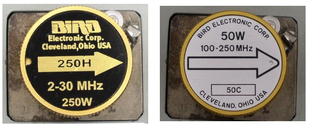
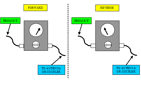
The watt meter is placed "in-line" with the co-ax run. Placing it in the system requires one or two extra co-ax jumpers and a connector adapter kit to match the jumper(s) with the different types of aircraft connectors. It also requires the correct "slug" to be installed in the meter. For VHF, the slug is usually 100MHz – 250MHz with a 25 -50 watt rating. HF slugs are 2MHz – 30MHz with a minimum of 200 watt rating. The arrow on the slug "points" down line towards the antenna for forward power and to the R/T for reverse power. With the affected radio selected and microphone keyed, the forward or reverse power can be measured. Typical aircraft VHF radios output approximately 15 watts. HF radios transmit around 150 watts.
Helpful Tips for Watt Meter Usage
- Placing the meter in-line with VHF systems can be accomplished at an intermediate plug break that is usually in the electronics compartment, or directly at the antenna. HF's might have a plug break, but the easiest insertion point is right before the coupler. The R/T rack plugs do not allow for system breakout.
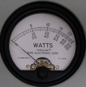
- Meter readings are arbitrary. A working system should have the reflected signal well less than 10% of the transmitted signal. 5% or less should be considered normal. A faulty co-ax or antenna will result in a much higher reflected reading.
- HF systems have extra components for antenna usage. The coupler is a tuning device composed of variable capacitors and inductors that "tune" the antenna for a selected frequency. The tuning process is indicated by a tone output on the speakers immediately after the microphone as been keyed. Watt meter readings should be accomplished after the tuning has completed. The system will repeat this process any time the frequency is changed.
- HF systems share the same antenna (not all the time). An isolation relay is used to protect (disconnect from the antenna) the unused R/T while the other is transmitting. This is accomplished at the back of the coupler rack. The watt meter cannot be used anywhere "aft" of the coupler.