The ILS or Instrument Landing System is a landing aid used to provide the correct lateral and vertical angles to the end of the runway. Glideslope and localizer information displayed with the deviation indicators is referred to as "raw" data. The navigation receivers provides this information. Additional outputs from the receivers are sent to the autopilot and flight director computers for "coupled" approaches. The flight director computer or FCC uses ILS data along with other inputs such as air data and radio altitude for display on the ADI flight director as "computed" data.
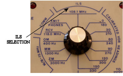
Testing the ILS system is accomplished with the VOR/ILS test box. Many different varieties of test units are used today. The basic functionality of them is the same. Most units use 108.10 MHz as a standard test frequency. This is actually the localizer frequency, but a matched glideslope output is also transmitted.
Tuning the aircraft's navigation control to 108.10 will place the receiver in ILS mode. If an aircraft is equipped with dual systems, placing both controls to 108.10 is helpful as a comparison of indications. Newer generation aircraft do not have a navigation control. Tuning of the navigation receivers is accomplished by the Flight Management System. Manual tuning is possible from the FMS control head. Honeywell FMS's have a line select key labeled NAV/RAD for inputting frequency and radial.
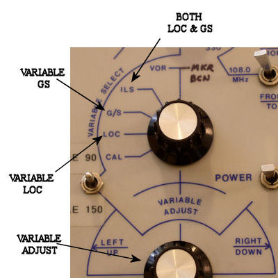
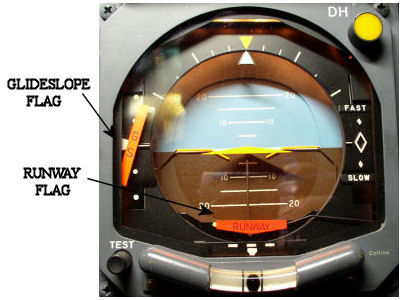
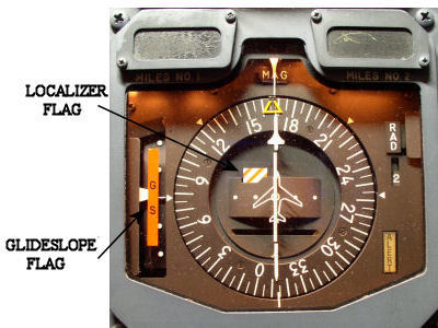
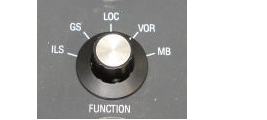
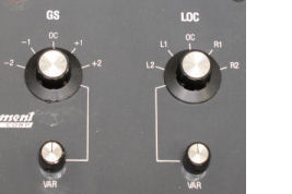
Select ILS on the test box. If the proper output is received, both the localizer and glideslope flags should pull out of view. Most testers allow for separate control of localizer and glideslope signals or both can be driven simultaneously. Full scale defections of either needle should be noted when the variable knob of the tester is used.
Helpful Tips for ILS Indication and Testing
- ILS indication or specifically the localizer does not care about compass heading. The course knob is usually set at runway heading by the flight crew or straight up when maintenance is using the tester, but if the course was placed right/left of centerline the indication would still be the same.
- Localizer deviation dots usually represent 1¼ degrees each for off centerline. Glideslope dots represent 0.7 degrees each.
- Most aircraft installations crisscross ILS information. The captain’s ADI and F/O’s HSI showing #2 nav information. The captain’s HSI and F/O’s ADI showing #1 nav information. Comparisons between systems should always be used if two are installed.
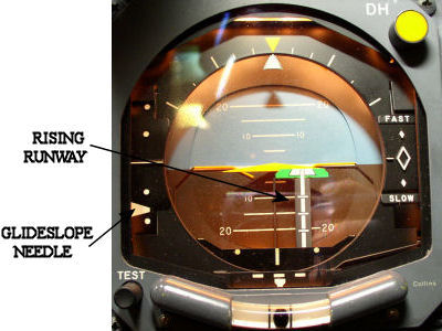
- The “Rising Runway” installed on some ADI’s is a dual indicator. Localizer left and right, with the dots representing 1¼ degrees. The vertical section is radio altitude, with full up representing "on the ground".
- Typical installations on aircraft have the glideslope antennas on the nose gear, nose gear doors, or mounted on the forward side of the pressure bulkhead. The localizer antennas (dual antenna for VOR and LOC) mounted on or near the vertical stabilizer. Getting the localizer flag to pull and driving the indication is difficult on larger aircraft with some testers. Opening a window and placing the test antenna outside helps, do not let it contact aircraft skin. VOR/ILS testers do not usually survive a fall from the window; some do not rest correctly on the window frame.
- The TIC30 VOR/ILS tester along with a few others allow for attenuation (decreasing) of the transmitted signal. This is very helpful when troubleshooting antenna or co-ax problems.
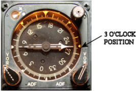
- Older aircraft with RMI’s that have the needles selected to NAV should “park” them at the 3 o’clock position when the navigation systems are tuned to any ILS frequency. This is a function of the navigation receiver.