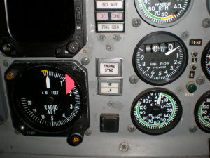
The engine synchronization system used on Gulfstream’s with Spey engines (GII and GIII) is used to match engine RPM speed. This alleviates the back and forth hums that can be heard when passengers are seated near the rear of the aircraft.
The flight crew can choose to match either LP or HP spool speeds. This system is used at cruise altitude only. It is not effective during climb or decent due to the large throttle movements needed for altitude changes.
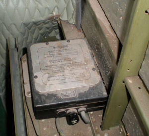
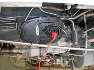
The
Woodward
system is used on Gulfstreams, but similar installations can be found on other aircraft types. The system consists of two cockpit switches, two control relays, amplifier, and the engine actuator.
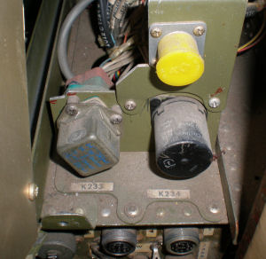
Each engine has two tachometer generators that feed their respective cockpit LP/HP indicators. These same signals are used by the engine sync amplifier. The signal input relay (K234 on GII's) will either input LP or HP dependent on the cockpit switch selection.
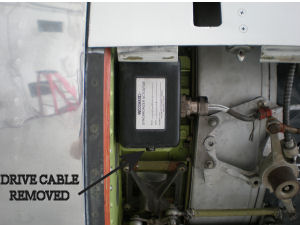
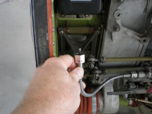
The engine sync actuator is mounted on the left engine. It is considered the “slave” engine. RPM inputs from the right engine are compared to the left by the amplifier. The left engine speed is corrected to match the right engine.
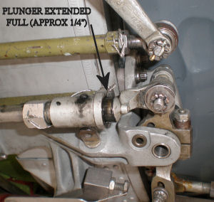
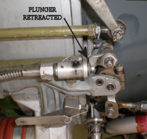
The actuator feeds a drive cable/plunger assembly connected to the throttle input section of the fuel control unit. Full plunger movement is approximately ¼” total travel which limits engine speeds match to about 1.5% of fan or turbine RPM.
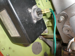
The actuator is basically a stepper motor. Activation in either the CW or CCW directions requires DC voltage pulses. The amplifier outputs 24VDC pulses to pins “A” or “B” of the actuator for the required directional rotation. Pin “C” is the ground.
When the system is turned off the amplifier will feed voltage pulses to pin “D”. This will allow the actuator to drive back to its electrical center and return the plunger to mid travel. This allows for full range use on the next engine sync application.
continued below....