Search Results (Searched for: lcr)

30 May 2025 10:17 - 30 May 2025 10:22
Please reference: rotate.aero/forum/ata26-767/319-ata-26-18-duct-overheat for troubleshooting of a similar problem.


EICAS status message "Right Loop 2"

The system is telling you that one of the two wing duct overheat loops has failed. In the case of duct loops, both loops have to sense a overheat to actually show a warning to the crew. If one loop is inoperative and the other loop senses heat.... it will set off the warning.

Body and duct leak issues are easy to identify the fault, finding it..... can be a major pain in the ass.

The easiest place to start is at the loop test panel on the P61 panel. Both ends of each loop (2 body, 2 left wing, and 2 right wing loops) can be checked from the plugs at the back of the panel.


We checked several loops with a LCR Meter . When compared..... all the known good loops checked had resistances over 250K Ohms. Our suspect loop had a meter reading of 1.9K Ohms.


Now comes the fun part of (my favorite three words in aviation) "Gain Access To" the loops themselves. This always involves dropping panels or removing sidewalls.


We checked for a open loop first (pin to pin on the plug). We found the loop still had continuity. If the loop reads good end-to-end, then our issue most likely was a short (or high resistance short) to ground. The measurements above were taken using aircraft ground as a reference. 1.9K Ohms seems high, but the system monitor card showed the loop failed.

To isolate the problem we disconnected the loops midway. Our short followed the inboard three sections. We could read that from the test panel plug. One pin showed high resistance (250K+ Ohm).... the other was still the 1.9K. We had to separate each of the remaining three loops and checked for a short directly at each one.


16 Feb 2023 16:25 - 16 Feb 2023 18:15
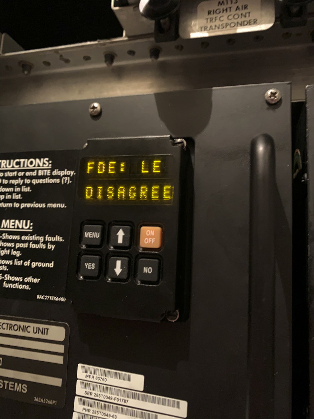
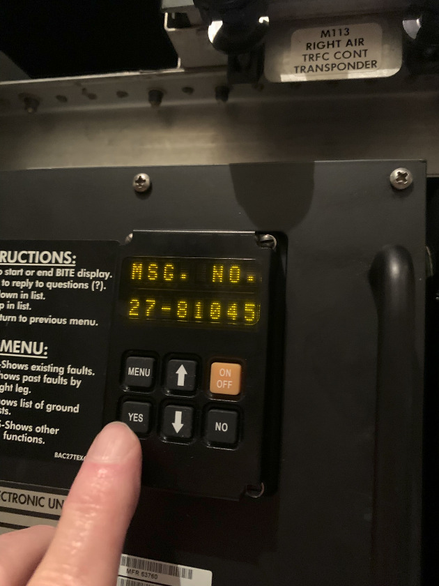
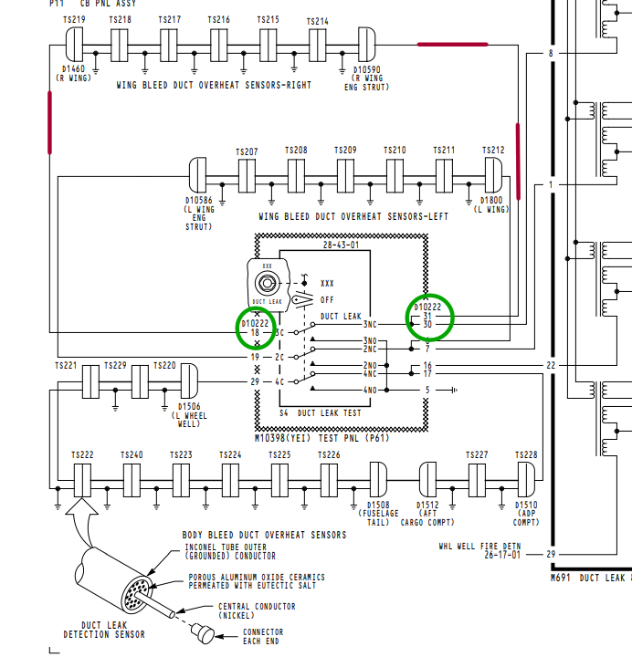
Some confusion has been generated when comparing Maintenance Manual proximity sensor requirements and actual readings.

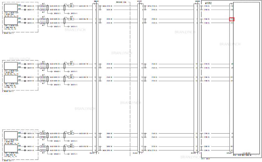
From B767 AMM, 32-09-13.


*******************


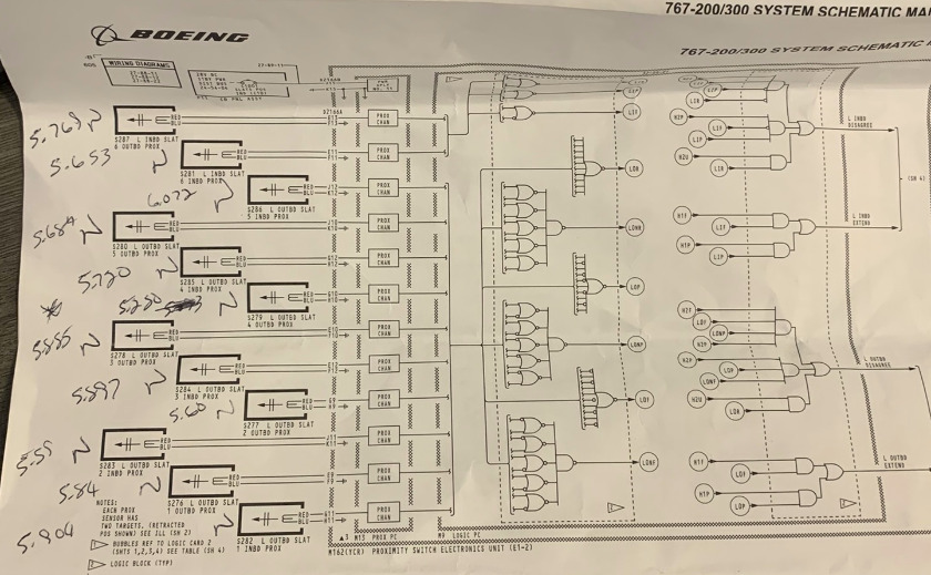
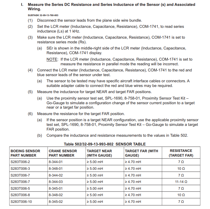
Boeing asks for resistance in the first chart and then states that readings are in mH or Millihenry. Millihenry is a measurement of inductance, not resistance. In the second chart they ask for inductance and resistance, but the readings don't come close to what our meters are showing.

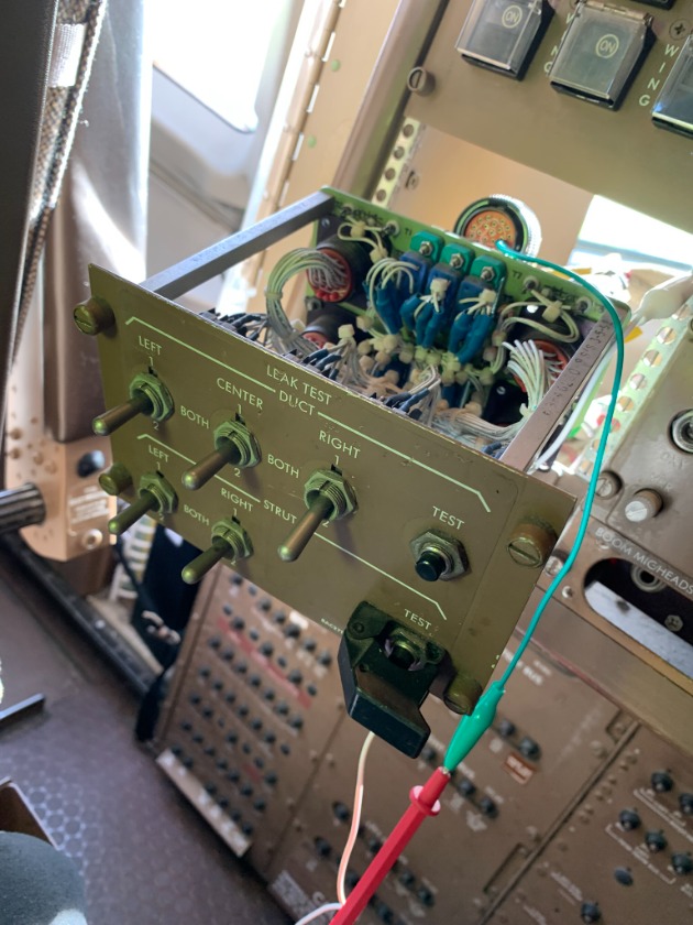
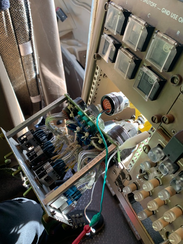
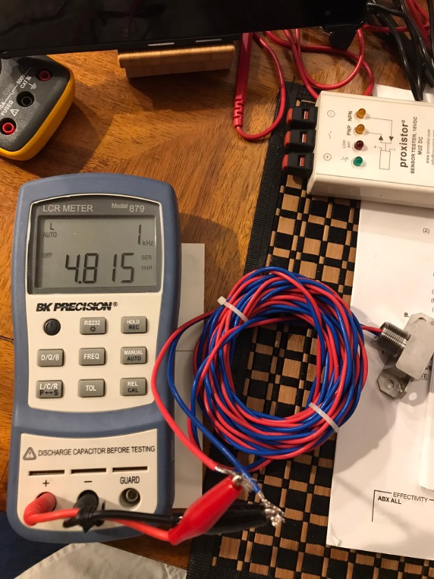
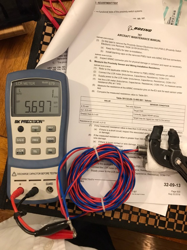
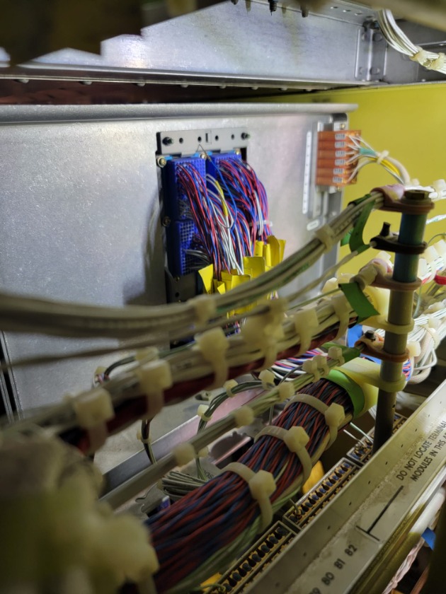
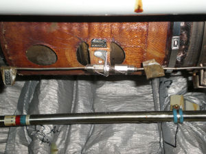
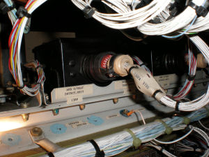
Resistance with the LCR meter is way out of anything stated by the manual. I'm going to trust our readings before the manual. The following images show actual results on the aircraft and in the shop.

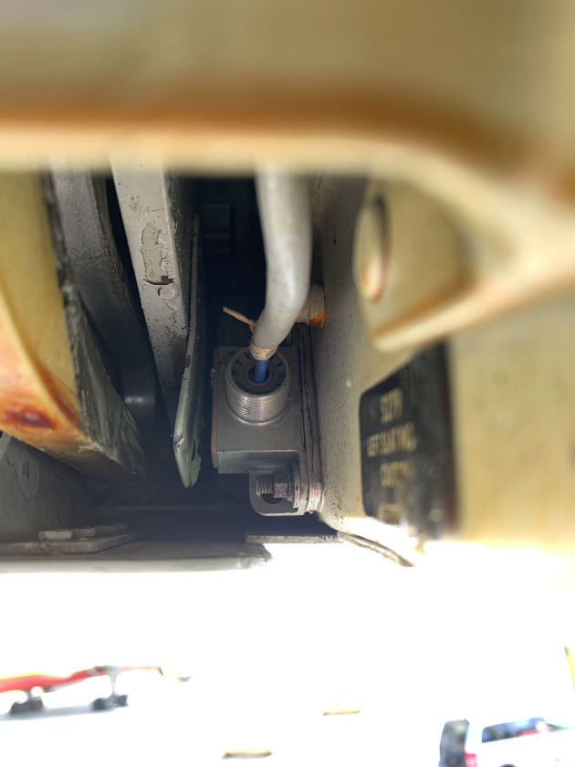
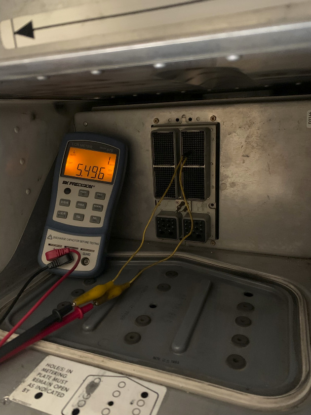
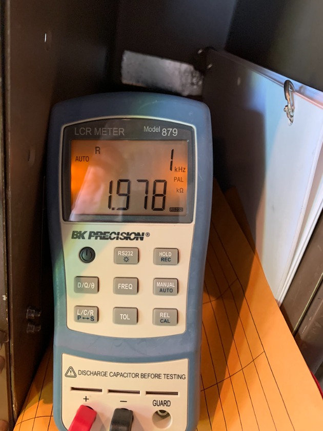
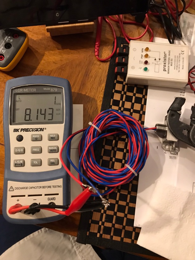
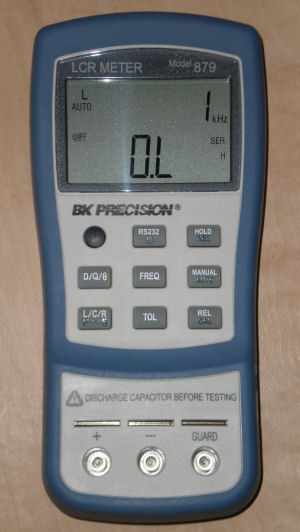
With the LCR in inductance set at 1KHz and the target far.....


Target near (using a folded napkin for spacing).....


 Target touching.....


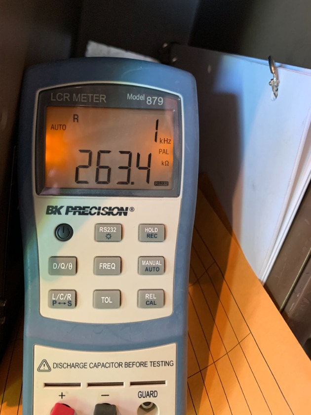
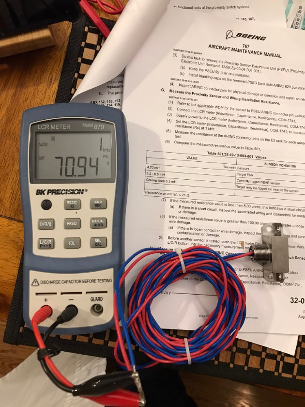
Resistance using LCR.....


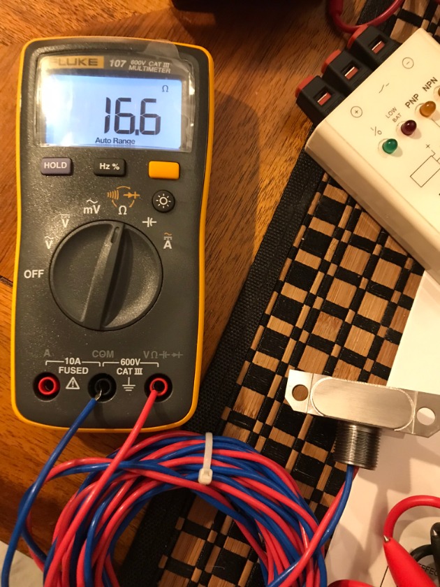
Resistance using VOM.....


In the case of targets near and far, these seem to fall within the readings shown in the first chart. As to what might cause the PSEU (Proximity Sensor Electronics Unit) to fail a sensor, we'll have to experiment on an aircraft one day. I would guess that laying a target directly on the sensor causing a high mH reading should be a failure.

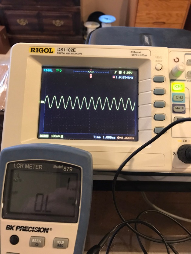
I had the time to look at the outputs of the LCR using an O-Scope and meter.

The waveform.....


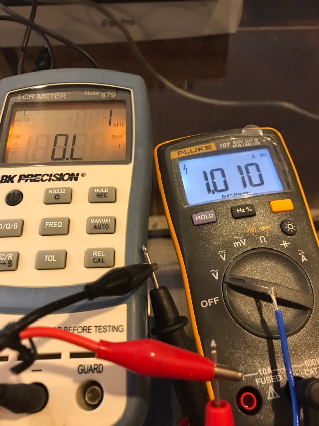
Output Frequency (the manual asks for 1KHz. It can be changed to higher on the meter).....
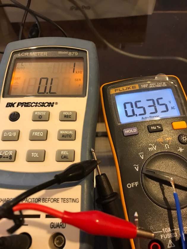


 Output voltage.....


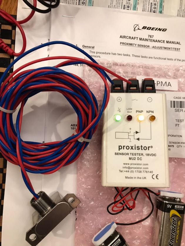
A unit called a Proxistor can also be used as a quick Fail/Pass tester on a sensor. Amazon link  here .


This unit is really setup for three wire units (as found on some Airbus aircraft). On two wire sensors, the PNP/NPN lights should be ignored. The green light represents a good unit.
19 Jan 2023 07:03
Replied by Mark on topic Thermocouples
When replacing thermocouple wiring, how do you know what color (green or white) is what material? 


Chromel (green) is magnetic. It should be attracted to a magnet.

We found the opposite for the pins. Alumel pins seemed to have a greater pull to a magnet.
 
23 Aug 2022 02:59 - 23 Aug 2022 03:03
LE Slat ASYM was created by OG GarlicSalt
Boeing 767-200 with intermittent LE ASYM EICAS message. This problem resulted in two air turnbacks and forced the aircraft to jettison fuel on both occasions. This issue was worked twice and a "fix" found both times by a repair station. After returning from MX we received the aircraft again and on its second trip out the message briefly popped up with the Flap/Slat position indicator bouncing between 0 and 1.

At this point I picked up the task and with the history associated with this I wanted to do a very thorough check of the system. I performed a BITE test on the PSEU and it indicated what should have been the faulty sensor. After noting this I still decided that I would ignore the finding from the BITE test and use an LCR meter to test every sensor individually. At this point I found pin F12 on the PSEU for the #3 LH O/B slat to be pushed back. After reinserting the wire and verifying the lock was holding, we closed everything up and no issues since.

What made this an odd find and what seems to have tripped up the repair station is that each time this problem occurred the PSEU faulted a different sensor than the one actually causing the problem. The PSEU indicated one sensor on the R/H OB, L/H IB and when I did the BITE in indicated 276 for the #1 L/H O/B while the fault was with 278 #3 L/H OB slat.

Wire came out after being lightly pulled not engaged with the lock.


29 Jul 2020 09:31 - 29 Jul 2020 09:31
Quick two wire proximity sensor check with LCR meter.


02 Aug 2014 11:06 - 25 Oct 2017 18:34

Airbus pneumatic leak detection systems require the use of an LCR meter for troubleshooting. The meter uses an alternating current (A/C) signal to measure inductance (L), capacitance (C), and resistance (R). Standard VOM’s use direct current to measure resistance and cannot be used to measure the impedance of inductors and capacitors. Also, the use of a standard VOM will produce incorrect loop resistance readings and the possibility of damaging the loop.

Troubleshooting a faulty loop system is fairly simple. With the LCR meter selected to resistance, a reading from either loop end to aircraft ground is made from the controller interface plug. Properly operating loops should have readings that are higher than 3K ohms for the wing and APU loops or more than 17K ohms for the pylons.

If a pylon loop is reading low from the controller, the reading must be taken again directly at the loop itself. This will isolate it from the aircraft wiring. Unlike the wing and APU loop systems, the pylon overheat system uses only one loop section.

Low readings from the controller for the wing and APU loops require a “halving” troubleshooting method. The loop system is split and the faulty side identified. The splitting process continues in steps until the actual faulty loop section is verified.

The aircraft wiring “to” the loops can also cause faults. With both loop ends disconnected, any reading to ground would be cause for further troubleshooting. Wiring shorts can be read with a regular VOM or possibly a megger.


The use of an LCR meter is required for troubleshooting of an “open” loop system. Also note that a “good” ground must be used when using the LCR meter. Most loops run close to aircraft structure which can be used for the meter ground (black) test lead. The BK PRECISION meter, like the one shown here, power up in the “L” mode. Pressing the “L/C/R” button twice will place the meter in resistance mode.


A300-600 ATA 36-22-00
Schematic 36-22-00
Maintenance Manual 36-22-00
Displaying 1 - 6 out of 6 results.
Time to create page: 0.906 seconds