Search Results (Searched for: Bleed)

21 May 2026 17:35 - 21 May 2026 17:40
Speed Monopole Failure was created by Mark
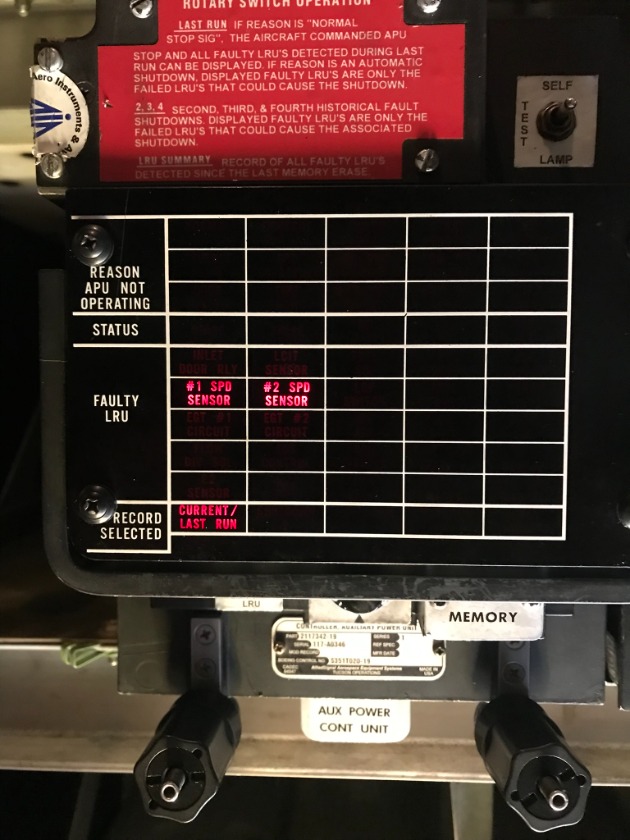
We had an APU that would not start. The RPM indication fluctuated wildly on spin-up. A dual monopole fault was recorded on the ECU (Electronic Control Unit).


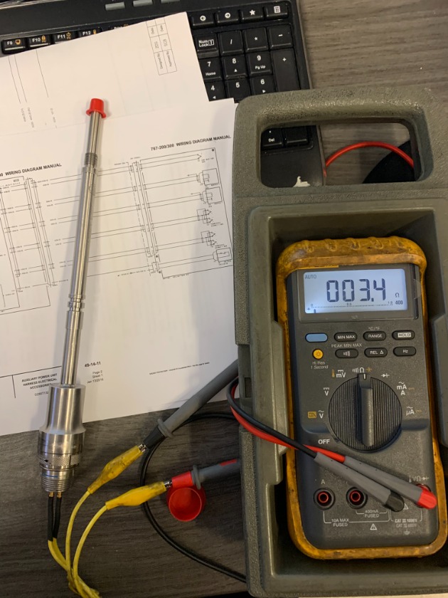
It seemed strange to have both monopoles fail. They don't use a common ground and their wires are completely separate. They both read around 7 ohms from the ECU rack back to the APU.

A new unit was checked, it came in just above 3 ohms. 4 ohms aircraft wiring resistance isn't bad for such a long run.


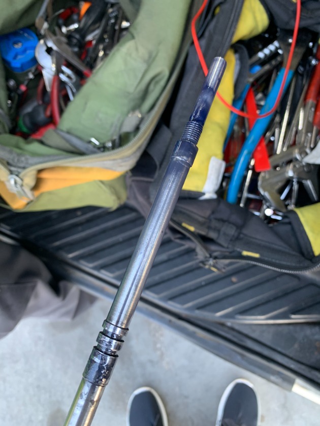
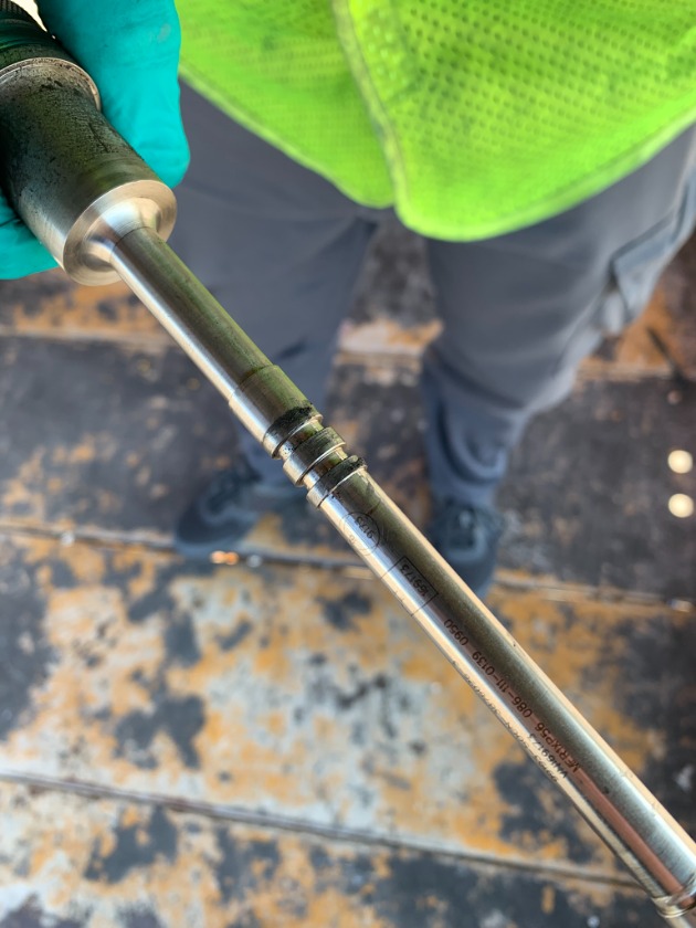
We pulled both monopoles. Neither had o-rings installed and the left probe was covered in oil.


The left probe was loose. It could be turned by hand. It was no where near close to being fully seated. It's threads showed signs of wear from moving around inside the case.


These probes are mounted 180 degrees out from each other. They are monitoring the same spool. If one wasn't fully seated I would guess it's output was slower (and different) from it's pair. The ECU received mixed signals. Not knowing the correct speed would be cause for a shutdown.

We replaced both (with the o-rings). All APU functions were normal after a good start.

As a note: the 767's APU is a single spool unit. Speed is a fuel control function. Bleed pressure is controlled by inlet guide vanes.

Some aircraft like the DC-10 and MD-11 are dual-spool units. There is a monopole for both N1 and N2 speeds.
  
  
03 Apr 2026 04:07
Good morning Mark,

I sincerely appreciate you giving me this great opportunity.

The issue began after another mechanic replaced the Kory switch, but the problem persisted. In addition, when operating the APU with the APU BLEED switch turned on, an autoshutdown occurred.

On the B747-400, there is a switch on the electrical bus page that allows you to open and close the bus. As you may know, it is similar to the GEN switches on the overhead panel (P5). I will provide more accurate references later if needed. There is also a separate switch in the P6 section that allows control of the bus. After operating this switch, we were able to determine that the issue was not related to the APU generator itself. This led us to confidently conclude that the problem was with the Kory switch on the P5 panel.

Many mechanics, when replacing a Kory switch, only replace the “guts” rather than the entire assembly. In this case, only the internal components were replaced, not the full assembly. During the replacement process, I found that the spring on pin 18 at the back of the Kory switch was not functioning properly. After replacing it, the APU GEN switch operated normally.

Additionally, I would like to share an easy troubleshooting method for APU autoshutdown on the B747.
30 Mar 2026 18:36 - 30 Mar 2026 18:48
I was asked for some help on a 747-400 APU generator problem by a new member Taekchang Lee, who is at CVG.

This was a double generator problem as neither would show "AVAIL" with the APU running.

I was wrapped up on another aircraft and I really didn't have time to look at the prints he sent me, much less give him any direction.

He sent me two video's from the aircraft. I'm including them here.

After I had a chance, I did follow up on the problem. The generator issue was corrected. Another one, APU auto-shutdown when air bleed turned on is addressed in the second video. It shows the electrical page with both APU generators showing no volts - no freqs.

I'll get with Lee to see if he can explain the repairs.  
        
 
19 Mar 2026 13:48 - 19 Mar 2026 18:33
Replied by Mark on topic Left Wing Duct Leak
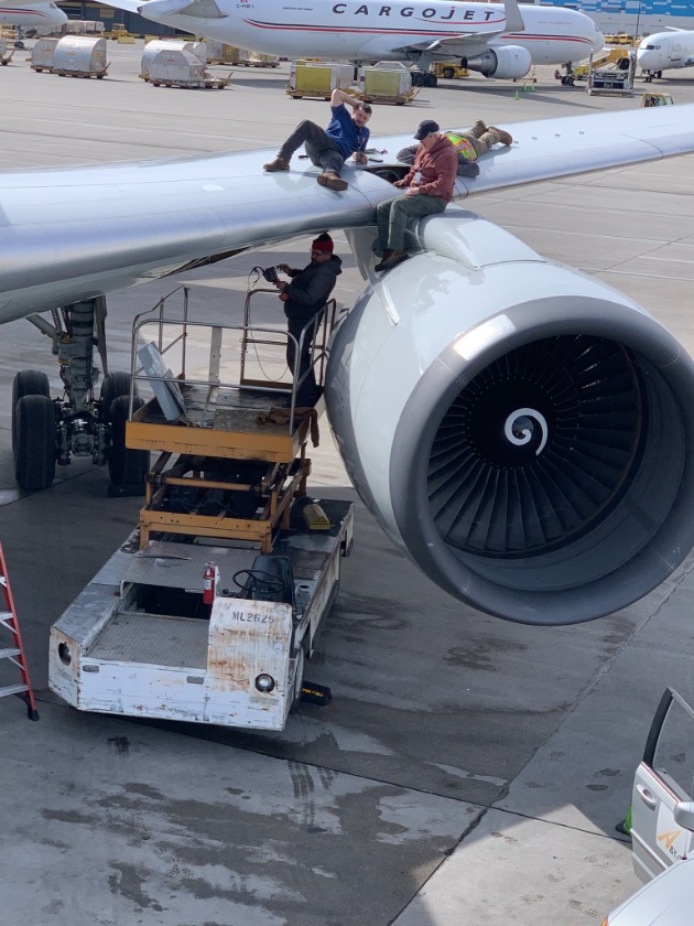
You didn't see "me" out there on the wing. Old folks like myself need the "young bucks" to do the lifting.....

Yes, it sucks. The first loop in the A/C bay is the only one reachable. All the rest require panel removal and a set of nimble hands to get over and behind the bleed duct itself.
18 Mar 2026 21:05 - 18 Mar 2026 22:14
Left Wing Duct Leak was created by Mark
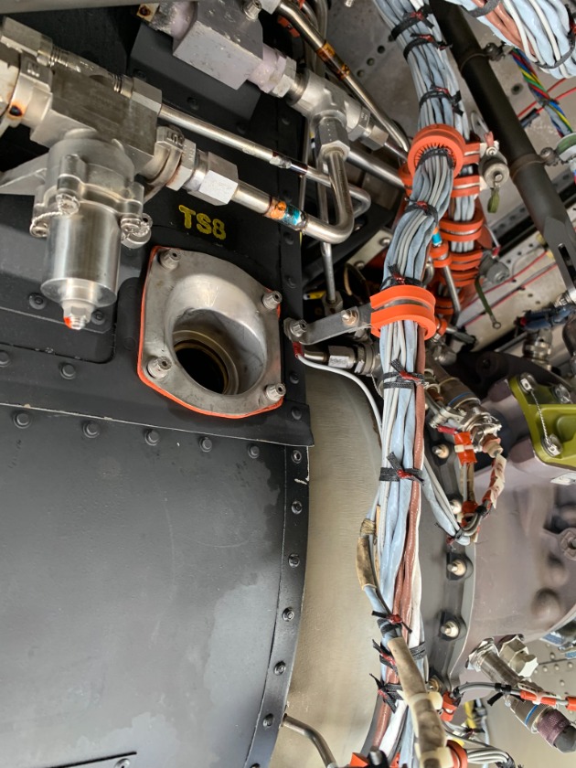
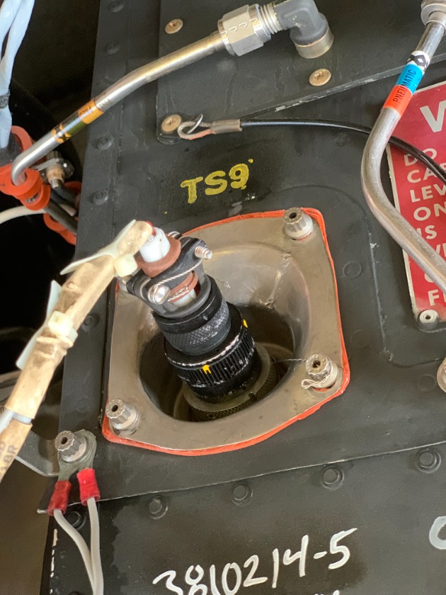
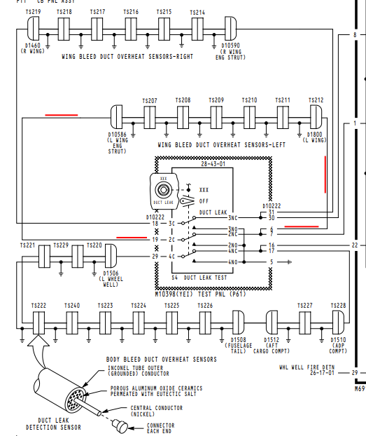
We had another problem similar to this one dealing with the left bleed air system. In the case of this particular aircraft, the overheat switches were part of a different warning system so we were dealing with just the loops.

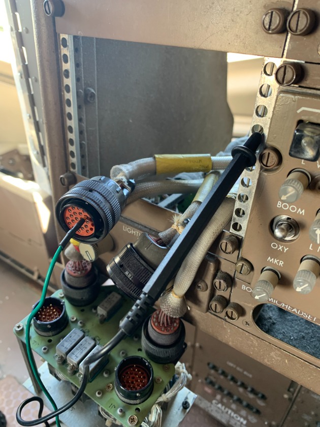
As with either type of configuration, everything can be checked from the system test panel. Both ends of each loop.... (left, right, and body) converge at the plugs behind the panel.


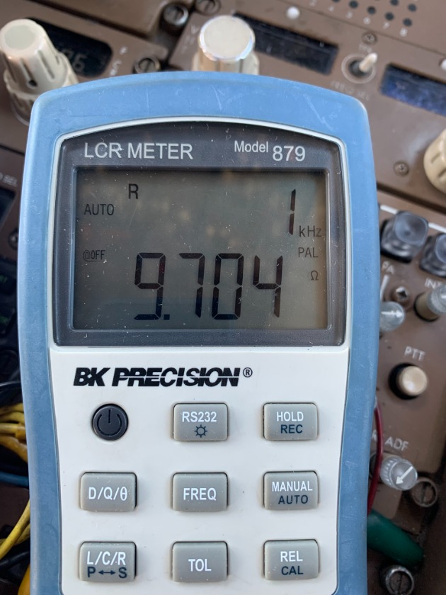
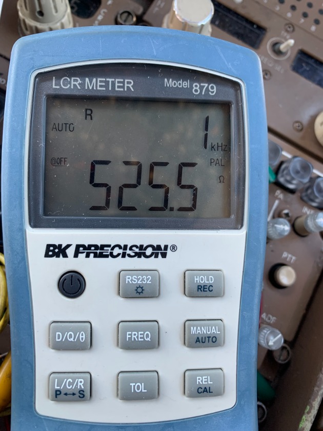
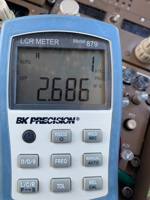
The reading from end-to-end of the loop in question was around 9Ω, which is a good reading.


A problem was noted when a short to ground was checked. Just over 500Ω while a known good system was 2.4MΩ+.


500Ω does sound like a pretty high resistance, but we're dealing with a static aircraft with no wing fluctuations from flight.

Now comes the "fun" part. If both ends of the loop show a short to ground, how do you trace it down?


You try to find an accessible point halfway in the loop series and disconnect the junction. The short will now only be on one pin. That takes you either outboard or inboard. Ours was outboard. When the next junction was separated..... the short went away. Meaning, the loop between the first disconnect and the second was bad.

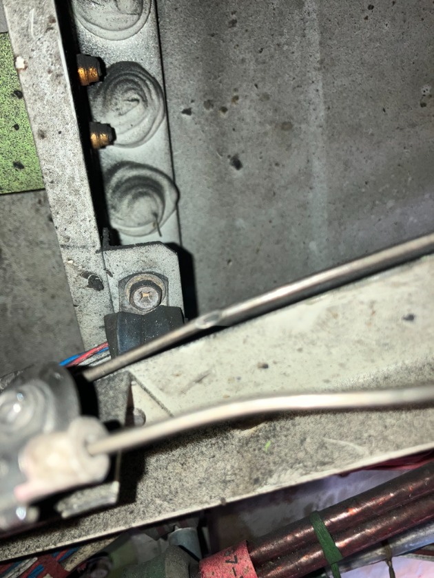
A bracket arm had broken free of its mount and had rubbed into the loop.


Gaining access to these connections can be quite difficult. The more "hands on deck" the better.....



16 Mar 2026 21:04 - 20 Mar 2026 16:06
Crew write-up(s) dealing with four fire warning systems.

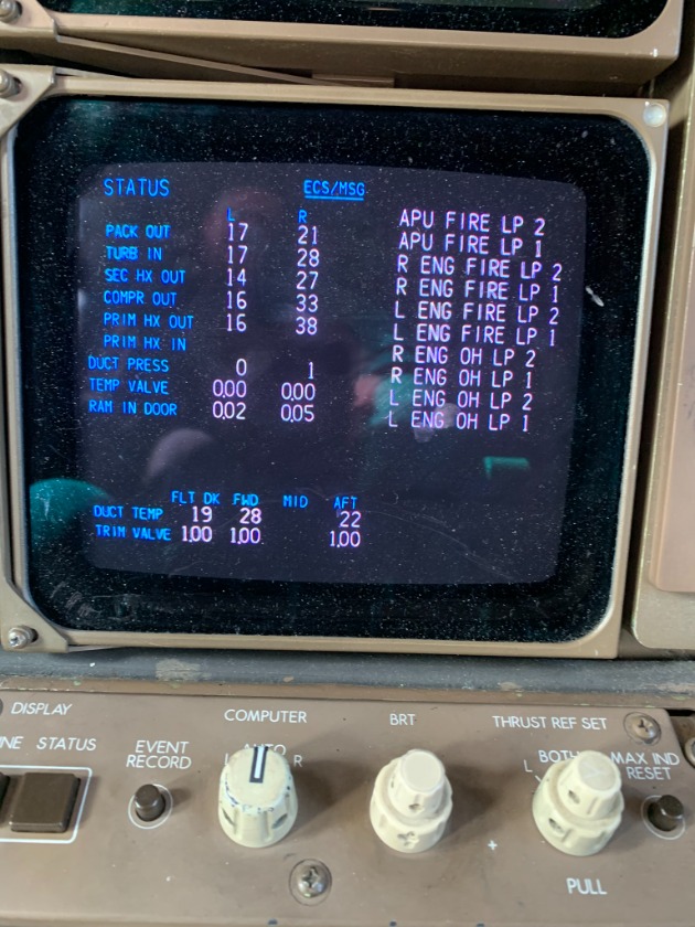
One APU FIRE LOOP, one LEFT ENGINE FIRE LOOP, one RIGHT ENGINE OVERHEAT LOOP, one LEFT WING BLEED LOOP. The second write-up was a fire system fail message on final.

When you dig into the problem, having four separate system faults at the same time seems odd. When tested, all of them passed..... meaning no actual loops were bad.


You have to look for something else in common with all of them..... that was the 28VDC power input which came from the RIGHT DC BUS. That leads you to the RIGHT T/R (or transformer rectifier).


Also of note, the issues with the loops happened on push-back. What is going on during that time? Engine start with power swap when the generators comes online. What was suspected on the fire system fail on landing? Auto-Pilot coupled approach where the A/C and D/C power bus's isolate from each other.

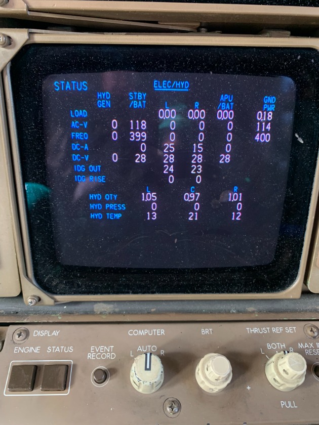
We compared DC voltage drop and recovery between the left and right T/R's during power input swaps. The right voltage dropped lower and took longer to recover. (Really hard to tell when everything happens in under a second.)

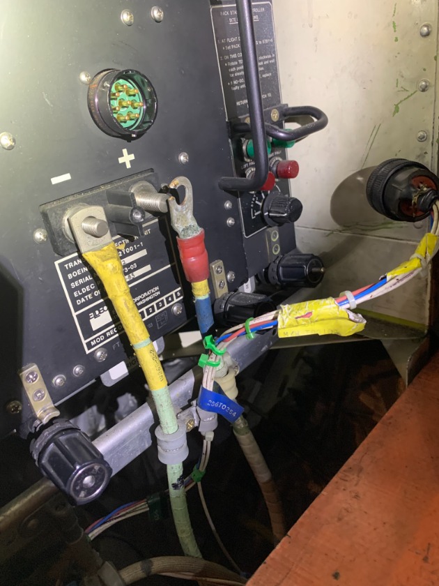
So..... when we went to replace the T/R....


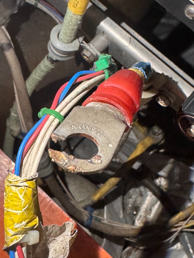
Lug nut not fully tightened..... and a burned terminal.


None of the items repeated except the left wing bleed issue. That turned out to be a hard fault that is discussed here .
05 Mar 2026 13:44
Replied by jochute on topic PRV Exit Pressure sensor
767 at purple promise, ahm is the "real time" boeing aircraft health monitoring system. There are no flight deck effects for this sensor, it just senses the bleed pressure after the pressure regulating valve but before the prsov. It will show -7 psi just about every single leg, with occasional psi spikes. Even with multiple sensors replaced it will still show -7 psi but the cockpit duct pressure uses the same 28vdc, I am just not sure if it is getting to this particular sensor.
Displaying 1 - 7 out of 7 results.
Time to create page: 0.923 seconds