I was asked to help with a #1 engine start problem on a GII. The problem was intermittent, but when it did fault, the planned flight was lost.
Both GII's and GIII's use the same model Rolls Royce "Spey" engine.
With out drawing up any prints..... it can be explained quite easily.
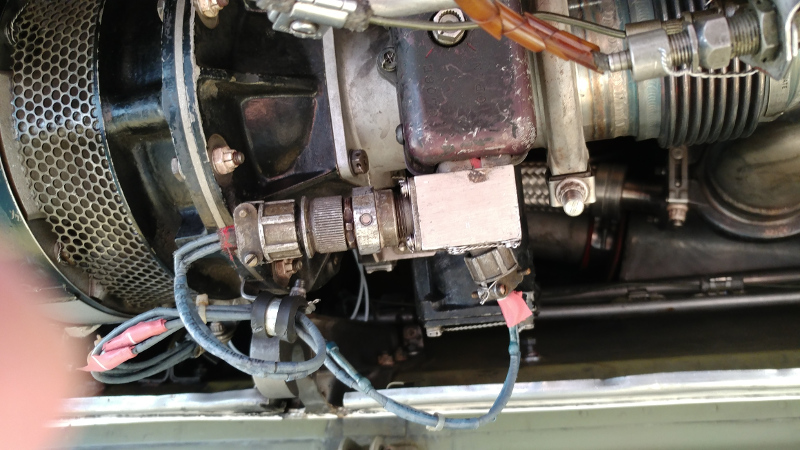
The starter has a centrifugal switch built in. (Switch plug not visible in this image. On the left engine, the starter is mounted inboard next to the pylon. The plug is at the 2 o'clock position when viewed back to front.)
This switch is normally closed until a set rotation speed is surpassed during start. Its only purpose is to provide a ground to the start control relay located in the 169 panel behind the entrance door. This relay, when energized, provides 28VDC to the starter control solenoid, initiates ignition, and stops generator cooling air. Those items will remain in that condition until the centrifugal switch opens up (engine at a speed where the starter and ignition are no longer needed). The relay de-energizes, the start valve closes, ignition stops, and generator cooling resumes.
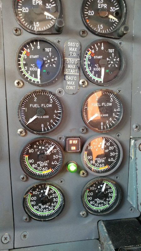
Engine at 14%. Start valve and ignition lights on. Green rotation light on.
Newer aircraft engines use engine sensors that feed rotation speed to the engine computer. The computer controls the start sequence.
GII AWM 80-11-00