Reading "Switches" In Components

More
2 years 5 months ago - 5 months 1 week ago #777 by Mark
This is wrong!!! Please see below.

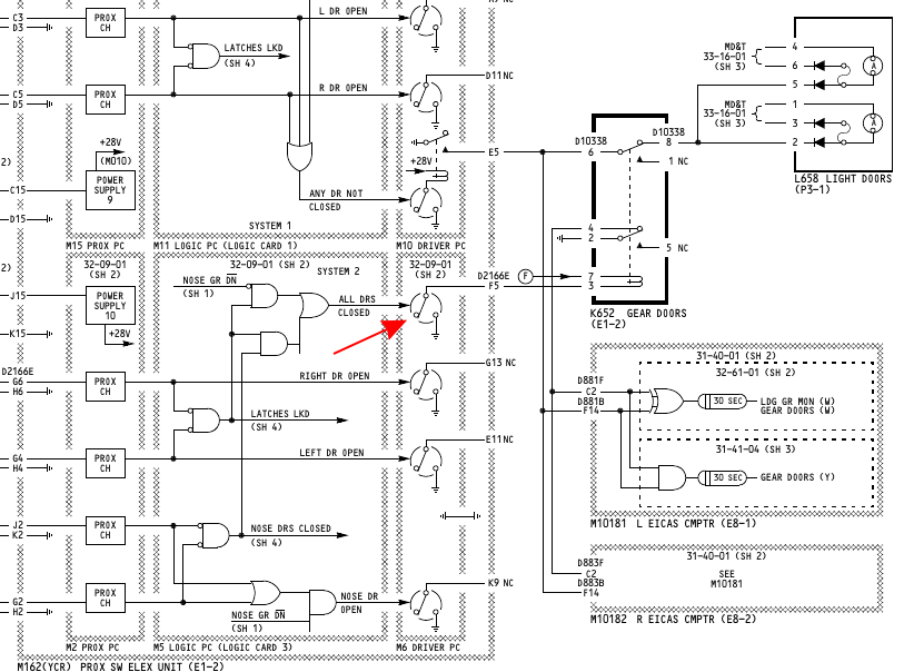
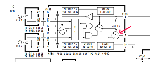
When checking for grounds through a component that shows switch type contacts enclosed in a circle, using a meter in  resistance mode will not read correctly.


The electrical theory behind how these work is beyond me, but I suspect we're looking at something like a silicon controlled rectifier that uses a "gate" to allow current flow.


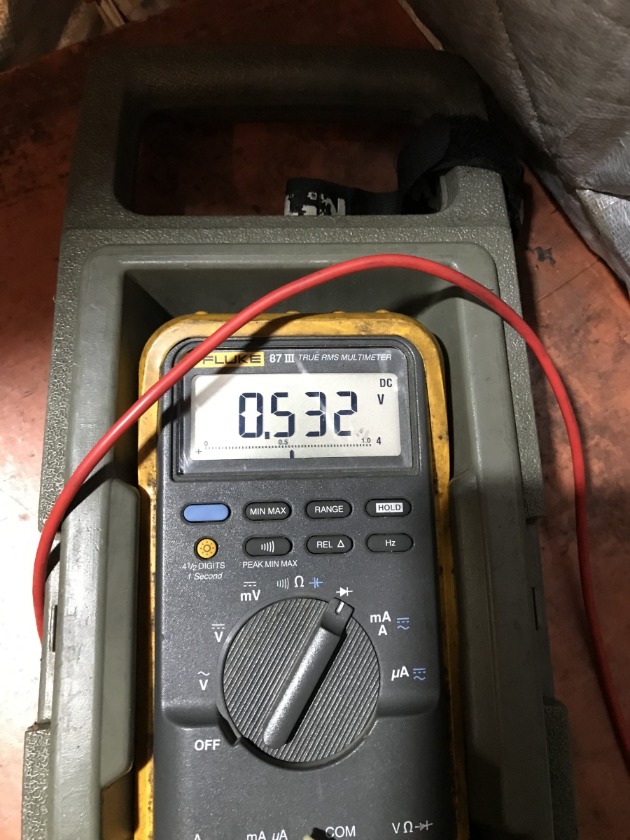
To correctly check for grounds through these devices, the meter must be selected to  diode  mode and the test leads must be biased right. You will be reading the "voltage drop" across the diode. Normally this is about .5-.6 volts. If you see this drop, the "switch" can be considered to be "on".


The Fault Isolation Manual states "check for ground" when referencing these devices. It doesn't state exactly "how" that ground reading needs to be taken.
Last edit: 5 months 1 week ago by Mark.

Please Log in or Create an account to join the conversation.

More
5 months 1 week ago - 5 months 1 week ago #1293 by Mark
I have discovered that my post above is not correct. I have not found a way (using a meter) to verify if a silicon controlled rectifier or transistor is "on" or not.


When accomplishing a diode check with the meter, I get the same results with a live circuit as I would with aircraft power off. Meaning..... you can't rely on on this type of check to verify if a active ground is being supplied through the card or circuit.

I'm guessing the current carrying capability of these ground signal components is rather small. They are usually used to activate relays which control other user systems downstream. [In the image above, a ground signal is used to control a relay that allows the valves to open for fueling operations. If fuel is present in the surge tank(s), the card removes the ground which causes the fueling relay to relax and kill power to the valves. This keeps fuel from spilling on to the ground.] A full explanation of this circuit can be found here .

I used a small peanut bulb (327 Bulb) as a signal light to verify if this particular ground signal was present or not. This is about a .1 amp draw on the system. (I'm guessing a typical relay coil is about .75 amp draw.) Using one of these small bulbs allows you to check the circuit without frying the card.


Last edit: 5 months 1 week ago by Mark.

Please Log in or Create an account to join the conversation.

Time to create page: 0.717 seconds