I was asked to troubleshoot a oil pressure indication that was fluctuating in flight. Having never dealt with this system before, I had to reference some manuals.
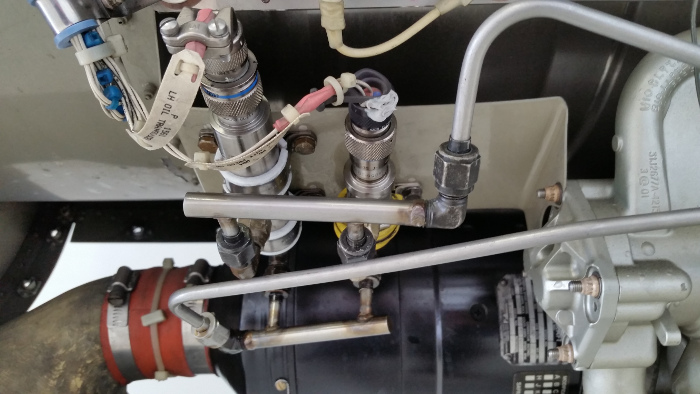
Engine left forward section. Oil Pressure Transmitter on the left and the Oil Differential Pressure Switch on the right.
From the maintenance manual I found a chart which showed how the indication was derived. I originally thought it was resistance based, but I discovered it's DC Voltage driven system.
From the chart:
PSI --- VDC
0 --- 0.0
50 --- 1.0
100 --- 2.0
150 --- 3.0
200 --- 4.0
250 --- 5.0
Cessna described a test harness that could be built to simulate the voltages (From AMM revision 27, 79-30-00-1, Pages 1-2). From what I saw, their harness would not work at all. The four pins on the transmitter plug are "A" 28VDC, "B" Signal +, "C" Signal -, and "D" Ground. Their harness did not tie into pin "A" so how was a simulated voltage to be achieved???
They wanted you to connect into pins "B" and "C" only. Their drawing was similar to the one below.
With this set-up, you're only going to get a variable resistance. They called for a 500 ohm potentiometer. I have absolutely no idea what the switch is for.
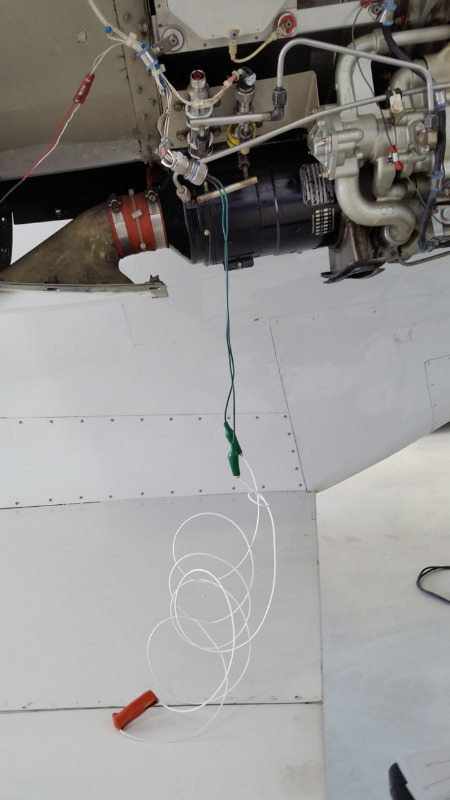
Instead of all this Mickey Mouse crap, it looked like I could use a battery to simulate this voltage. All the indicator wanted to see was a positive and negative DC signal. I wasn't sure if it would work, but I gave it a shot anyway.
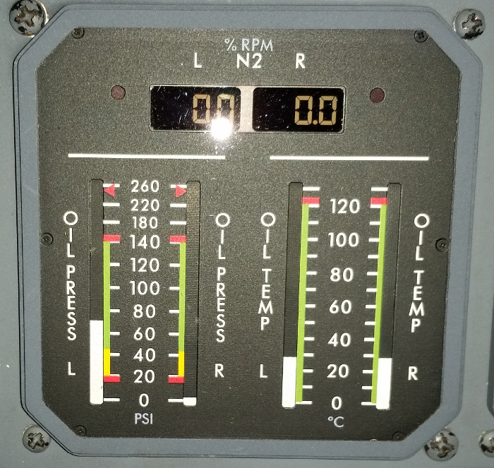
I had this on the indicator (1.5 VDC equalled approximately 75PSI)
This would of been a whole bunch easier with a variable DC power supply or a battery holder pack in which more batteries could be added in to increase the voltage.
I'm betting all Garrett 731's use the same system.
Model 550 Bravo AMM 79-31-01-2
AWM 77-10-01-01