Checking wire continuity or component resistance is a simple task. The majority of avionics/electrical troubleshooting requires the ability to decipher meter readings correctly.
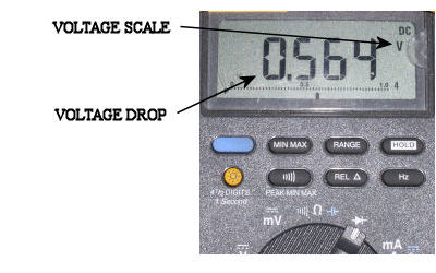
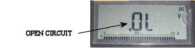
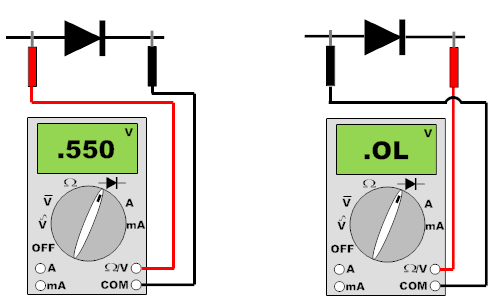
Diodes are solid state devices used extensively throughout aircraft avionics and electrical systems. They are basically a "check valve" for electrical current, allowing flow in one direction only. To verify the condition of a diode, one leg should be isolated from the system. Having the test leads in the forward bias position the meter will read the
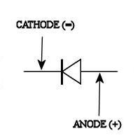
voltage drop across the diode (the meter displays "V" instead of "Ω"). Typical indication is from .5 to .6 volts. With the leads swapped, the meter will read open. The easiest way to remember the bias, the diode "points" to ground or negative. The diode will have a white band on the negative side.
Some sensors installed on aircraft have diodes installed in "series" with resistors. Fuel level sensors are an example. When checking these from the fuel level amp, the meter will have to be selected to diode check to verify proper continuity of this type of sensor.
There have been many times that I have been continuity checking wires only to have the resistance reading jumping around in the 1MΩ range. If this is noticed, flip the meter to diode check to verify if one is in the system. Schematic diagrams often omit showing diodes that are installed.