
- Posts: 1106
- Thank you received: 191
Fuel Quantity Test
9 years 1 month ago - 8 years 8 months ago #385
by Mark
Fuel Quantity Test was created by Mark
Aircraft fuel quantity indications are capacitance based systems. Troubleshooting and calibration of these systems is accomplished with the Fuel Quantity Test Unit. The tester measures tank and probe capacitance, accomplishes resistance checks, and provides simulation for tank quantity indication. (As of late, many never aircraft types have dropped the capacitance measuring system in favor of newer technologies.)
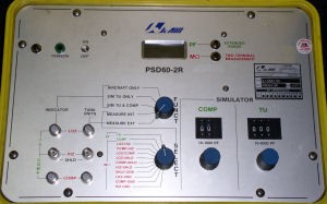
Fuel quantity test boxes are made by numerous manufactures. All will have similar switches and functions. The tester shown here is JcAir® “PSD60-2R.
STARTING WITH THE BASICS
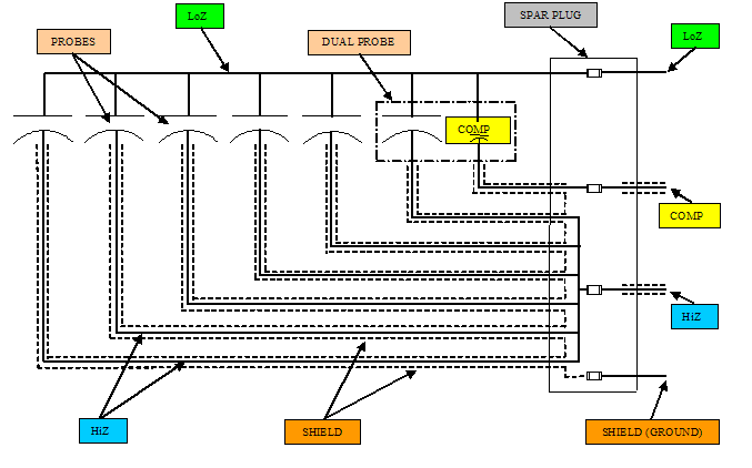
- Most aircraft fuel tanks have numerous fuel quantity probes installed. The number of probes used can vary depending on tank size and system design. Most common configurations have 6-12 probes. These probes are arranged in a parallel circuit.
- Each probe is a capacitor. The capacitance value of the probe will change with fuel level changes. The higher the fuel, the higher the capacitance.
- The input signal that feeds all the probes is called LoZ. The output of the probes is referred to as HiZ.
- Fuel capacitance is read in picofarads or pf.
- Capacitance in a parallel circuit is additive.
- Tanks have one probe that measures fuel density. This is the Compensator Probe. The “comp” probe has a unique function, but its output is still read in pf.
FUEL TANK CAPACITANCE CHECKS
Fuel quantity test boxes are made by numerous manufactures. All will have similar switches and functions. The tester shown here is JcAir® “PSD60-2R.
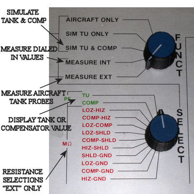
- Tank capacitance checks are run with the mode selection in MEASURE EXT.
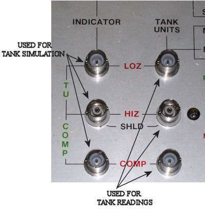
- Each aircraft type usually has a breakout box with all the matching plugs to connect to either the spar plug or indicator. Breakout box connection configurations will differ for aircraft type, but all will have the same outputs for the fuel quantity tester. The co-ax connections are HiZ, LoZ, and Comp (numerous breakouts have only HiZ and LoZ, the Comp is included with the rotary switch selections).
- If the test setup is connected at the indicator, only total tank and compensator readings can be made.
- If the breakout box is connected at the spar plug, each individual probe can be measured along with total tank readings.
- Tank or probe readings can be done with meter test leads, but the hookup requires having the correct spar pin-outs. Using the proper breakout box is still the preferred method.
- The fuel quantity unit’s TANK UNIT co-ax (BNC) connections are differentiated by gender. LoZ and Comp are male pins. This reduces the chances of incorrect setup (if the LoZ and Comp are swapped, you’ll know it).
- Tank or probe capacitance readings will not be correct if the ground leads from the fuel quantity tester to the breakout box and from the breakout box to aircraft structure are not connected.
- All tank and probe readings need to be made with the tank completely empty. Some tanks will require sumping. The Comp probe is located at the lowest point, if it is still sitting in fuel, the capacitance reading will be high.
- Total tank and probe capacitance values can be found in the aircraft's Maintenance Manual.
- A major function of the fuel quantity unit is measuring insulation resistance or a “Meg Check”. Different combinations of shorts can be detected. Minimum values for meg check readings will also be found in the M.M.
TANK SIMULATION
- Simulation of tank values is used for troubleshooting of indication systems. It is also used for calibration of some types of fuel systems. For calibration purposes, the simulated value is used along with the tank to adjust the “full” value of stand alone indicators.
- Tank simulation is a two step process. The simulation values need to be set up first and then the box switched to simulate mode.
- All simulations use the INDICATOR co-ax plugs. LoZ, HiZ, and Comp require correct connections.
- Simulation values are set with the mode select switch in MEASURE INT.
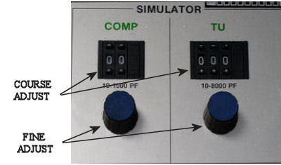
- Tank unit and comp values are dialed in with the course and fine settings of the tester. The thumb-wheel indication does not match actual values. The display should be monitored when setting both tank and comp.
- After the values have been set, the select switch is placed in SIM TU & COMP. The unit will output the dialed in values and the screen will show dashes or eights.
Helpful Tips for Fuel Quantity Testing
- Fuel quantity indication problems can be located anywhere in the system. I will exhaust ALL avenues before opening up a fuel tank for troubleshooting. Been there, don’t want to go back. Only a bad probe reading or failed meg check from the spar plug would be cause for accessing the tank.
- Meg checks usually verify problems with the tank harness. Fuel can migrate into an older harness and cause shorts in the wires. Probes rarely, if ever short out.
- A low or nonexistent probe capacitance reading is normally caused by a bad connection of one probe terminal. This connection must be made properly (screw, washer, terminal, and then probe) and it must be secure
- It is not unusual to have probe readings that are slightly (+/- 5pf) out of M.M. tolerances. These reading are normally on the high side. When a tank is drained of fuel, some will remain on the walls of the probes.
- Simulation of tank fuel quantity from the spar plug to the aircraft is useful for troubleshooting non-tank related problems. Empty tank simulation can be easily accomplished. If “fuel on probes” simulation is needed, I use the opposite wing tank values for HiZ and Comp. Simulating these values for whatever fuel level needed must be correct. The Comp, once it is wet will stay the same for all quantities. The HiZ will vary with fuel level. If either is not simulated correctly the aircraft fuel indication will most likely show an error.
- Newer generation aircraft send tank quantity signals to a central Fuel Quantity Computer. Each tank quantity is calculated and sent out via 429 data bus to all the systems requiring quantity information (EFIS, FCC, TRC …etc).
- Douglas products incorporate a junction probe that can be accessed from the top of the wing for isolation of probe or harness problems.
- MD-11’s or any other aircraft that allows making one tank probe inoperative from CFDS use a different type of quantity computation. They do not add capacitance. All probes are monitored individually. A modified average value is taken for quantity calculation. Loosing one probe will make the system less accurate, but a reliable quantity is still available.
Last edit: 8 years 8 months ago by Mark.
Please Log in or Create an account to join the conversation.
6 years 9 months ago #605
by Mark
Replied by Mark on topic Fuel Quantity Test
The importance of the ground wire from the test box to the aircraft when checking tank probe capacitance.
Please Log in or Create an account to join the conversation.

4 years 2 weeks ago #800
by minhas1
Replied by minhas1 on topic Fuel Quantity Test
Can I perform this test with the tanks full if I was troubleshooting for a fluctuation error? I don't really need to see the capacitance values, just need to see if a number for a particular probe is stable or fluctuating?
Please Log in or Create an account to join the conversation.
4 years 2 weeks ago #801
by Mark
Replied by Mark on topic Fuel Quantity Test
You've got to move the fuel around while checking. Transferring fuel won't cut it as the values will be changing as fuel leaves the tank.
Fluctuations are caused by bad probe terminal connections or a bad harness. These are seen in flight, rarely on the ground with a static plane.
What type of aircraft???
Jump on the wing if you can. Push-pull it with a tug.
Get the fuel sloshing around somehow.
Fluctuations are caused by bad probe terminal connections or a bad harness. These are seen in flight, rarely on the ground with a static plane.
What type of aircraft???
Jump on the wing if you can. Push-pull it with a tug.
Get the fuel sloshing around somehow.
Please Log in or Create an account to join the conversation.
Time to create page: 0.882 seconds
Don't have an account?
Register now to join the community!
©
2026
Rotate.Aero