Cessna Sovereign, Model 680, with Pratt & Whitney 306C engines, with a failed #1 engine fire detection system. The aircraft had spent some time in the rain before the problem showed up.
Usually, a engine run is all that is needed to blow excess water from the fan bypass area and let engine heat evaporate the other areas that might be hiding water in places unseen. A run did not cure the problem.
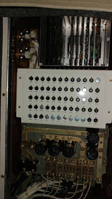
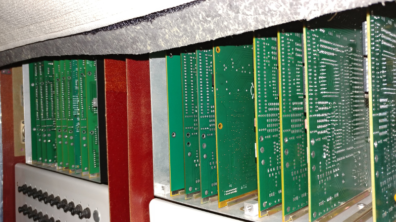
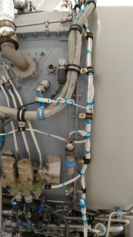
Next on the list was a re-rack of the #1 fire detection card and/or a swap of #1 and #2 cards if needed. The cards are located behind the forward wall of the aft baggage pit.
The problem was still present after a swap.
With the #1 card out, the rack pins "can" be accessed. but it took removing a fuel card just to the left of the fire card to enable a hand into the area for ease of pinning of the plug.
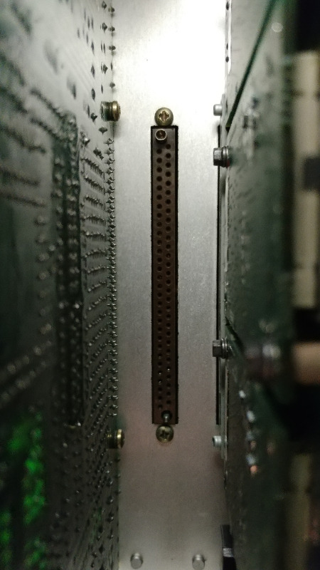
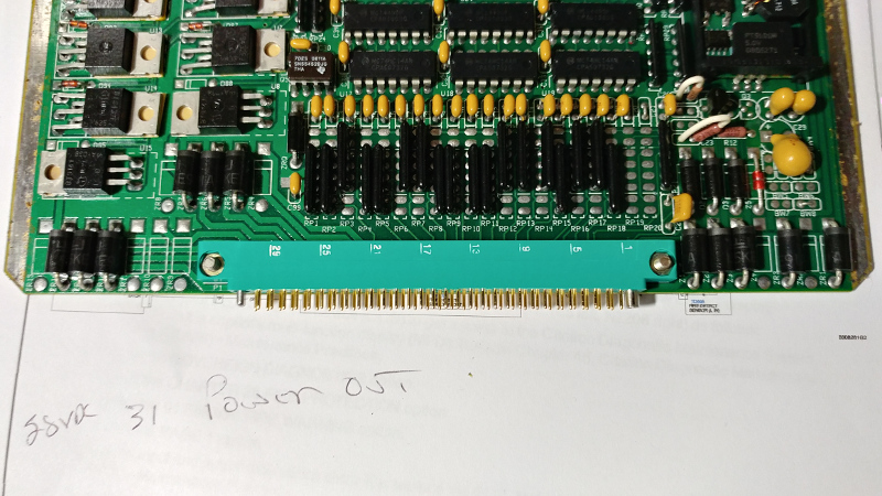
With my crappy eyesight, I could not verify if pin numbers where stamped on the face of the rack plug. The card did have pin numbering listed on the side. Looking at the rack plug, pin 1 (bottom) to pin 30 (top) are on the left. 31 (bottom) to 60 (top) are on the right.
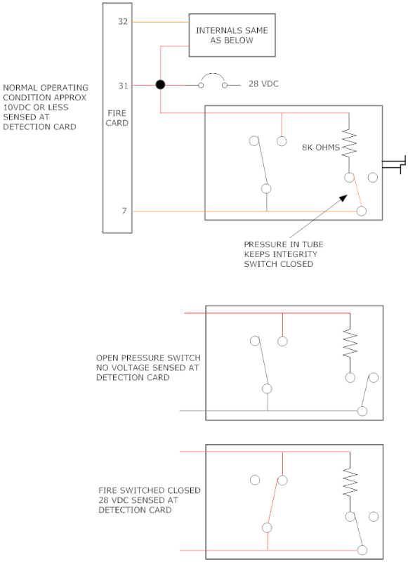
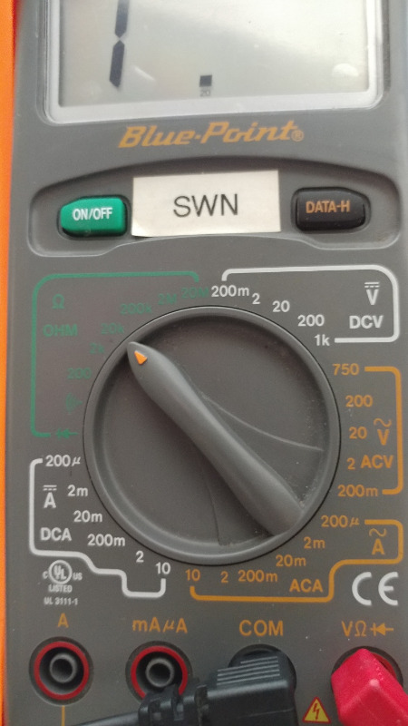
Only 3 pins are needed to verify the two loop's integrity. 31 and 32 for the case sensor. 31 and 7 for the core sensor. Each sensor should read 8K Ohms +/-800 Ohms. The case showed sensor showed good. The core sensor was open.
We verified the reading from the firewall plug "out" to the sensor...... still open.
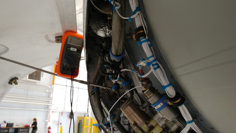
The core sensor cannot be seen externally and we had a tough time finding exactly where the plug leading into the core was located. A phone call solved the problem. It was right in our face the whole time.
Image shows core plug hanging (mid upper left). It's about a foot away (11 o'clock) from the case sensor plug (lower middle).
Checking the sensor directly at the plug showed it was open. We did check the wiring of both sensor plugs back to the card plug. We also shot the case sensor directly at the sensor plug.
A significant gutting of engine components will be required to replace the core sensor.
A brief explanation of how the sensor works, is needed. The sensor tube is pressurized. If pressure is lost, a switch in series with the integrity resistor goes open. The fire card is looking for approximately 10 VDC or less through the resistor to verify the sensor's condition. With a pressure loss, this voltage is not present and the card sends a signal to the cockpit of a detection fail. This was our fault.
In an actual fire condition, pressure in the tube increases to a point that the fire warning switch closes. The card senses 28 VDC which triggers a fire warning.
Cessna 680
AMM 26-10-30-1
WDM 26-10-01-5