Inbound MEL for the TCAS being inop. Second write-up in 30 days. Flight fault showed a couple Upper Antenna "J1" faults. A replacement was sent with the aircraft.
One "nice" difference between freighters and people haulers is that there are no ceiling panels on freighters. Access to the upper antenna connectors just requires a ladder.
I guess you can call this lazy or smart (I'll take the latter, but the former is most likely correct), but I'm not going to drag my happy ass on to the top of a MD-11 to replace an antenna without at-least reseating the co-ax connectors. Which I did.
The system was not failing when the aircraft arrived and it wasn't after messing with the connectors. I cleared the MEL. I'll watch it for a while...... if it fails, I'll smack the egg across my face myself.
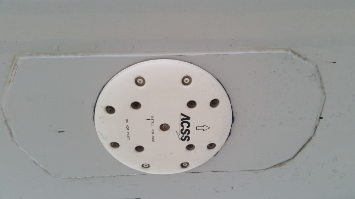
Picture of bottom TCAS antenna.
The antenna has four segments (each with its own co-ax connector). Each segment is a 90 degree pie wedge. The TCAS processor sends and receives data via the upper and lower antennas. There is a whole lot more than which pie segment receives the strongest signal from a nearby aircraft to detect relative direction. I just group this with A/C pack ACM's and describe it as PFM. Wrong!!! (Updated 4/22/25)
Please reference Farisha Farid's response at
www.quora.com/Why-is-the-top-TCAS-antenn...enna-omnidirectional
for a better understanding of the directional antenna.
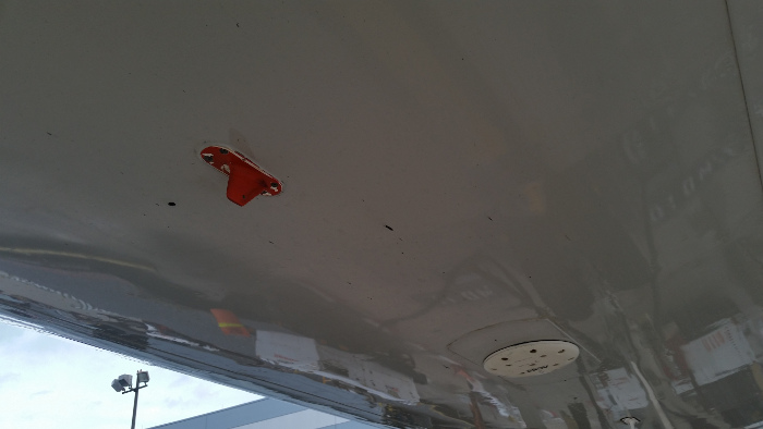
The ATC transponders use a smaller antenna that I call a Shark's Fin.
The TCAS, ATC, and DME systems transmit and receive in a very tight frequency band. 1030MHz and 1090MHz. While one is "talking", the others are suppressed. In the old days the ATC's and DME's had an external co-ax for suppression...... now, they're all incorporated in the rack plugs.
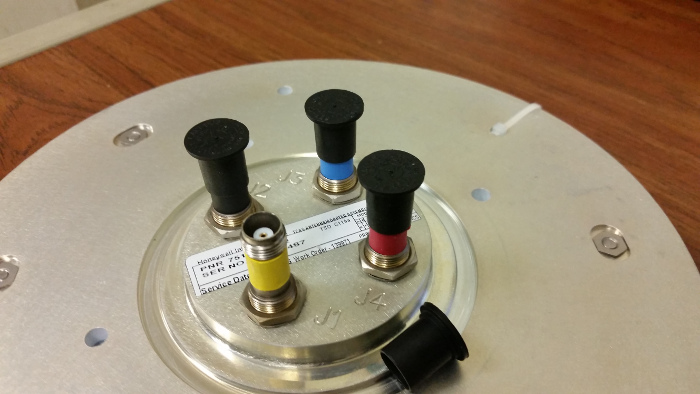
An image of the back of the TCAS antenna. Each element has a different resistance reading and each can be shot from the TCAS Processor rack plug. If this particular aircraft was failing...... I'd be doing some meter work at the rack before digging out the lift truck.
MD-11 AMM 34-46-00-0-99 (TCAS Discription/Operation)
AMM 34-46-00-5-99 (Adjustment Test)
ASM 34-46-00