Just for easing location identification of the individual loop connections on a CF6-80A engine.
There are two completely separate fire loop systems on each engine. It can be difficult to identify exactly which loop you're messing with.
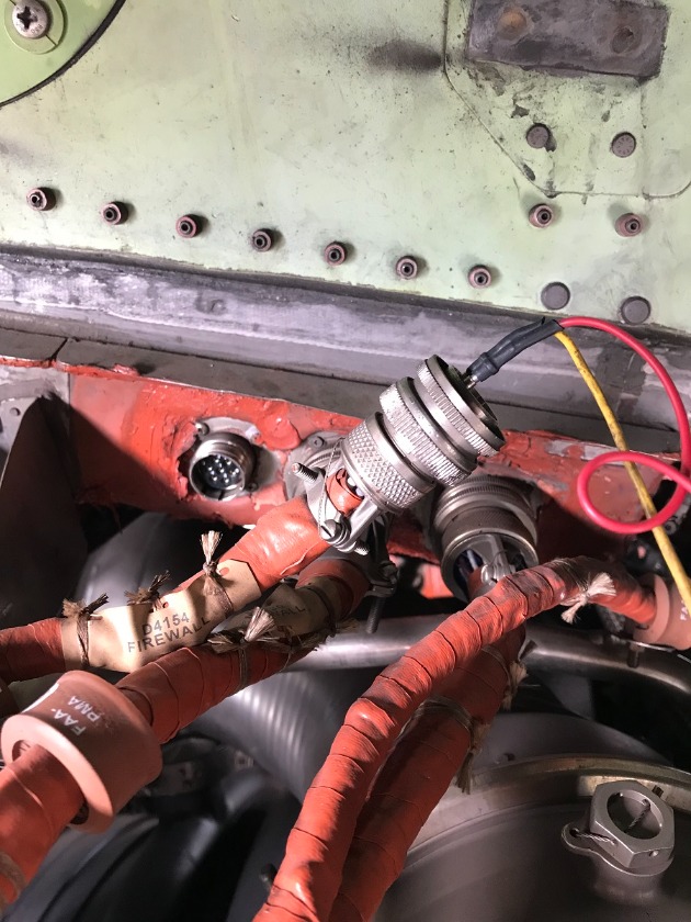
For the #2 loop system, the pylon disconnect is D4154P (Pins 2 & 3). Plug located on the right side of the pylon disconnect area, aft plug.
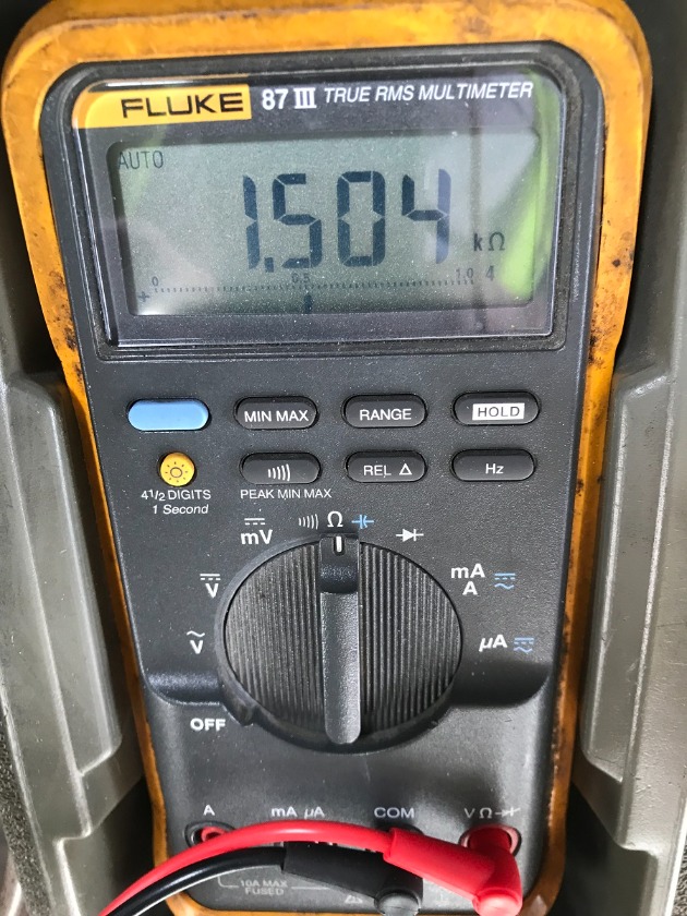
For all three loop sections, the total resistance is approximately 1.5K ohms.
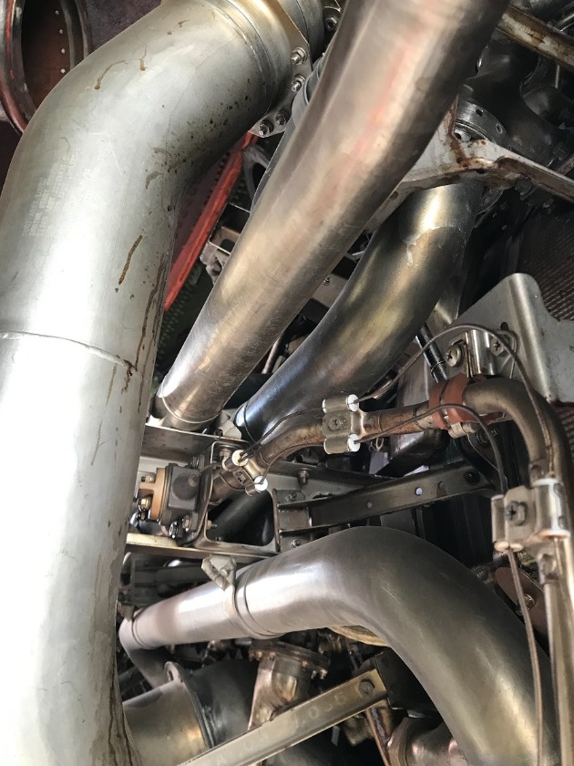
Engine left.... around 9 o'clock (looking forward).
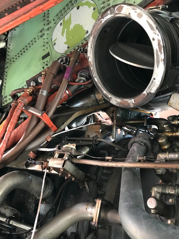
Engine left.... around 10 o'clock. (Just slightly forward of above image and below fan air cooling inlet duct.)
On the bottom center. Above and forward of drain masts.
These loops are in a parallel circuit. When either lead of any loop section is removed.... total resistance will go up (as explained
here
). Just watching the meter as I loosened the nuts was enough to show a fluctuating reading.