Front Release Plugs 


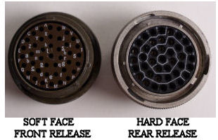
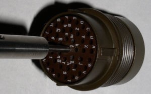
Front release plugs are found on older analog based aircraft. Newer generation applications use rear release plugs for most applications. Both types of plugs use locking tabs around each pin. The tabs must be spread open for the pin to be removed.


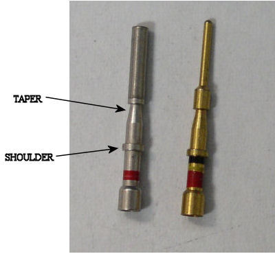
A quick visual of the front face is all that is needed to differentiate between the two. Front release will have rubber on the face and rear release will have a hard plastic material. Front release pins have a noticeable taper in diameter that starts after the shoulder.


The standard ranges of pin sizes are red, blue, and yellow. Red pins for gauges 18-22 receive the majority of use.


The most common purpose is for signal wires. The larger blue and yellow pins are found for power functions. It is not uncommon to find intermixing of pin sizes in the same plug.


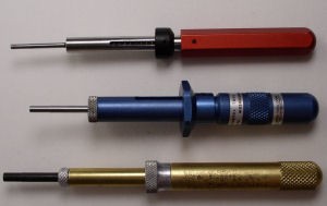
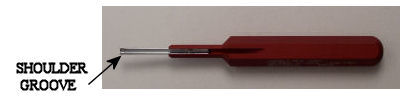
Front release plugs use a pin pusher tool to remove the pins from front to back. The tools are made by several manufactures, but they all work in the same fashion.


front4


 front1
front2
 front3  front5


Quick Notes on Front Release Plugs


  1. Selection of the proper tool color is an easy task. The pin diameter will dictate which color to use. The possibility of a mistake is slim. When the tool is placed around the pin the fit should be snug.
  2. The tool should be inserted and fully seated around the pin. A definite stop will be felt. Pin push tools can be rotated left/right to assure a full seat is made. If the tool has not been placed properly, the locking tabs will not be expanded and the pin cannot be removed.
  3. Pin extraction is completed by pushing the plunger. If the pin has a wire, a moderate pull will help to remove it fully from the plug. If no wire is present, a stick pin or paper clip from the plug front will help complete the extraction. Grabbing the base of the pin with needle nose pliers from the plug back is not recommended. If the base is deformed, it will call for rejection of the pin.
  4. A pin is placed into the plug with an insertion tool. The tool will have a groove at the end that is designed to fit around the pin base. A small click will be felt when the pin is seated and the locking tabs engage. If the wire gauge permits, I will use the wire alone for insertion.


Plug Numbering and Replacement


  1. All plugs that use letters for pin identification do not use "I" , "O", or "Q".
  2. Plugs that use numbers for identification will have parentheses "( )" around every tenth digit.
  3. Plug replacement requires extreme care. Any mismatch of pins can be cause for headaches when trying to verify the mistakes. I do not follow the letters or numbers around the plug. Most plugs will have the pins aligned in rows. It is much easier to start at one edge and do one row at a time. This prevents problems near the end of the plug change, trying to stab pins into the middle with wires all around. Each pin needs to be double, and then triple checked before moving on to the next one.
  4. Placing pins in the unused positions will help the "next guy down the line". If a pin is needed but not available in the shop, a spare can be used from the plug itself.


THE INFORMATION PRESENTED ON THIS SITE IS TO BE USED AS A GUIDE

APPROVED AIRCRAFT MANUFACTURER MAINTENANCE MANUAL PROCEDURES SHOULD ALWAYS BE FOLLOWED.