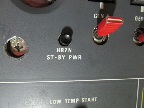
You hope the use of the standby horizon in flight will never be needed. That would pretty much be a SHTF situation of complete power loss. Needless to say, it still needs to work.
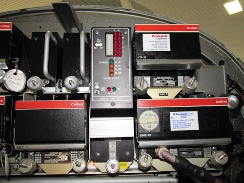
On this Falcon 50, the standby instruments and radios are powered by two separate power supplies located in the nose radio rack. This particular aircraft designates the #1 emergency power supply for the standby horizon. The #2 is used for background lighting on the standby altimeter and airspeed indicators along with power for one of the communication radios, one ATC transponder, and one navigation receiver.
The wiring prints show no tie-in between these two systems.The #2 power supply is armed with a switch in the pedestal. The #1 is automatic via a air-ground function. Gear proximity sensors place relay 25F in either a ground or air mode. In the air, if a power loss occurs, the #1 power supply uses its internal battery for horizon power. This DC output also keeps the power supply on with a command signal being fed through the closed contacts of 25F when it's latched in the air mode. On the ground, the relay has open contacts on the control wiring so that the power supply doesn't stay on when ships power is removed.
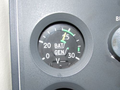
The test mode latches relay 25F in the air mode. Power supply voltage can be read on an overhead voltmeter and the horizon should remain powered. (Ships power needs to be on before the test button is used. Nothing should happen with test button use on a dead aircraft.)
Air-Ground Proximity Switches (two per gear)
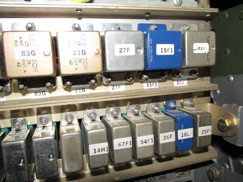
25F,26F,and 27F in left forward relay panel (26F used for background lights, energized for normal use. Fail-safe relaxed for emergency)
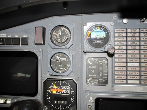
Standby Instruments
Overhead Voltmeter and Test Switch
#1 Standby Power Supply
As a quick note: The maintenance manual has you slug the right gear prox switches to simulate air mode for a functional check. A quick way to verify operation is to press the test switch (latches 25F in air mode), then reach up and pull the circuit breaker. When the switch is released, the horizon should remain powered. Pushing in the circuit breaker puts 25F back in ground mode and the horizon reverts back to ship's power through the power supply itself.
Falcon 50, ATA 34-20
Wiring Manual 34-21-00
IPC 34-23-90-20
Maintenance Manual 34-23-90-20