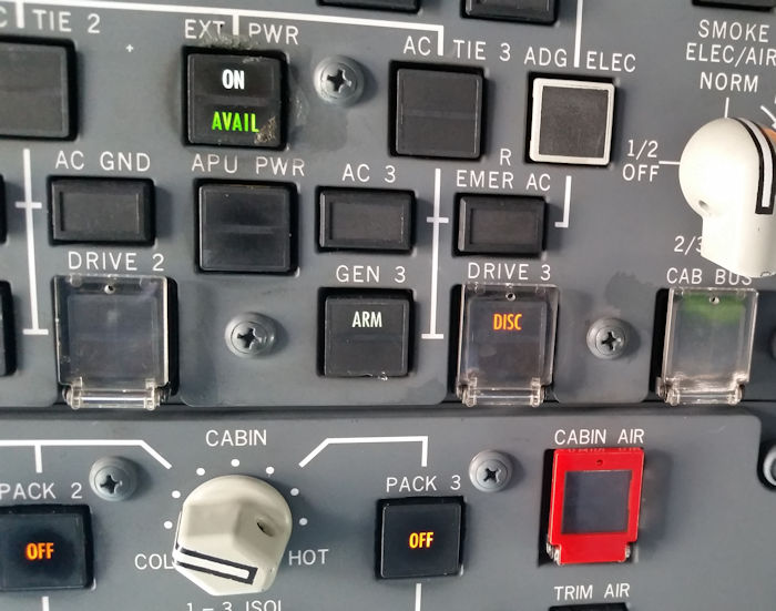
On a maintenance pre-departure check, a mechanic saw two electrical errors on the overhead panel. The #3 Eng Gen "Off" and the #3 CSD "Disc" lights were illuminated. A replacement GCU (Generator Control Unit) did not correct the problem.
Per the MEL procedures, the #3 CSD was disconnected and the aircraft dispatched.
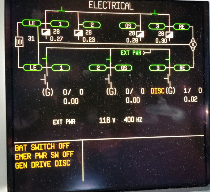
When I approached the aircraft, I found these indications for both the electrical page status and the overhead.
The troubleshooting was not mine, but the thinking was that the CSD underspeed switch was at fault. The reason behind this was if the underspeed switch was showing the CSD running, but there was no output power...... the GCU would interpret this as a fault and generate the fault lights observed by the mechanic.
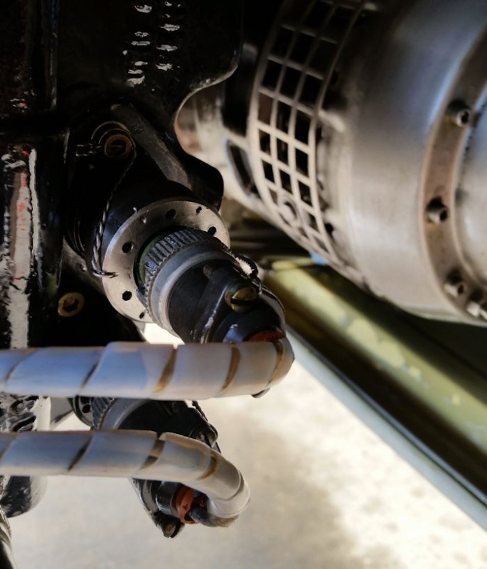
Given the choice of changing the CSD or......
changing the switch, it was quite obvious which we going to try first.
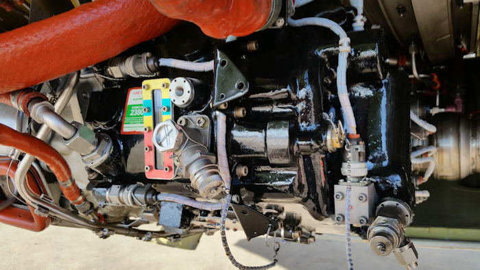
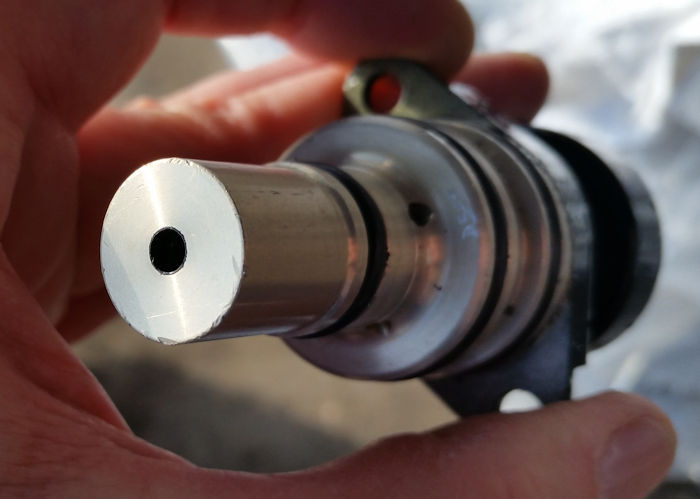
The switch is located on the forward side of the CSD. The replacement was quite simple and quick.
After re-engaging the CSD and starting the engine, the generator showed online with no faults indicated. (This picture shows the generator output of 115VAC and 400Hz. The #3 generator contactor is closed and the #3 bus-tie contactor is open.)
I'm somewhat perplexed as to the switch's operation. In the schematic manual, 24-21-1 and 24-11-2, it shows the switch coming off an output leg of the generator's PMG (Permanent Magnet Generator) with the resultant signal feeding the GCU. It appears the switch is activated by oil pressure which pushes down on a plunger. The plunger acts upon a coil inside the switch. The only thing I can guess is that the coil's inductance is changed with the position of the plunger???? No explanation is given in the Maintenance Manual.
MD-10-10, CSD Underspeed Switch R&R, AMM 24-11-06-2