Without digging into prints. I'm taking this all from my failing memory banks, so if anyone can correct me.......please do.
In the system shown in the video, I'm pretty sure the amp is the main "computing" component. Without gutting it, I'm sure there is a row of synco's that outputs information to all the user systems - RMI and HSI for the compass indication, but also outputs for the nav receivers, auto-pilot, comparitor, and maybe even the FMS's.
The sync indicator "is" on the RMI, but the amp is commanding the gyro torque motors.
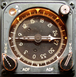
With an old RMI (C4 or C14 type???) like this one.
The RMI is the workhorse. The Compass Rack would have two removalable amps, servo and slave. There would also be a circuit breaker on the front face of the rack. This breaker is the 26VAC for the flux valve. The
HUGE issue with these older systems is the plug connection at the RMI. A plug that isn't seated "fully" will cause all kinds of crap to occur with the compass system or outputs. ( I did a road trip to Austin on an MD-80 to fix a bad #1 compass. My fix???? Pull the capt's RMI, verify no bent pins, and re-install plug
TIGHTLY. Problem solved and I still had some time to go slug down some beers.
 GII ATA 34-20 ???