ATA 26-10, A300-600 GE Fire Detection

More
9 years 8 months ago - 9 years 8 months ago #21 by Mark
A300-600 aircraft with GE engines:

Fire loops are installed to alert crew members of a fire or overheat situation with the engines. The usual configuration for larger aircraft is two complete systems for each engine. The physical loop “runs” are side by side to each other. For an actual fire warning to occur, both systems must sense the fire. If only one loop system senses a fire, a “loop” failure indication will be alerted to the crew. An aircraft can be dispatched with one complete system inoperative. In this case, if the remaining loop senses a fire, the full fire warning is triggered.

Loop systems are labeled “A” and “B” and each system (on this aircraft) has four separate loop segments wired in parallel. When a fire or overheat condition actually exists, the internal loop gases heat up and close a warning switch. A loss of any loop segment during flight does not disable the warning functions of the remaining three.


During a system test, the loss of one or more segments from a loop assembly will result in a test failure. Each segment has an internal resistor with a set value. The fire warning controller verifies total circuit resistance. If the value is not within a allowable tolerance, the controller will indicate a failure.

Total resistance in a parallel circuit will ALWAYS BE LESS than the segment (resistor) with the lowest value.


The easiest troubleshooting procedure is to disconnect the pylon plugs and compare “A” to “B” total resistance values. If they match, the problem is most likely on the aircraft side. If they don’t match, suspect a loop or wiring harness problem.


This particular aircraft had “B” system inop. A resistance check from the pylon (down) showed one loop assembly at 1.4K ohms and the other at 6.6K ohms. The loop segments were isolated from the wiring. Each loop “pair” had matching resistance values. The problem was an open wire in a harness. When read from the pylon, only one loop (the forward gearbox loop) was being measured. The open wire removed the aft three segments from the system. The controller sensed this high resistance value and indicated a loop system fail.


A300-600 ATA 26-12 Fire Detection
Maintenance Manual -- 26-12-00
Schematic Manual -- 26-12-00
Troubleshooting Manual - 26-12-00
Attachments:
Last edit: 9 years 8 months ago by Mark.

Please Log in or Create an account to join the conversation.

More
9 years 5 months ago - 9 years 5 months ago #34 by Mark
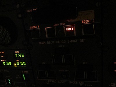
Numerous years and many-many lost brain cells, I again had to troubleshoot a engine fire warning system. Same as above with "B" loop being inop. We had a hard fault (good thing) on the overhead.


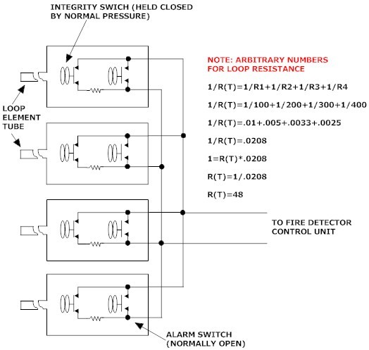
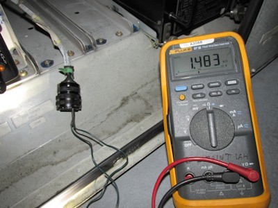
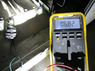
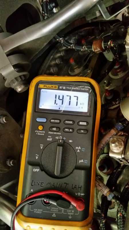
We gained access to the controllers and shot each loop system. Loop "A" was 1.4K ohms thru pins D and R (as you count the pins...... "A" is not marked but it aligns with the main key-way and there is no I,O,or Q). Loop "B" read 6.8K ohms. Both loops on the opposite engine read 1.4K also.


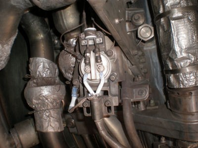
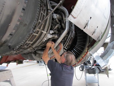
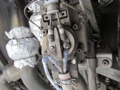
Out on the engine we wanted to break the loops in half. This "was not" convenient to do. The easiest break point was the lower turbine element. Breaking into the system here was a 3 to1 split with the gearbox loop being the 1 and the remaining 3 being all the turbine elements. We disconnected one wire from the "lower" lower turbine loop connector. Located engine right about 5 o'clock. This isolated the two sides. It is also important to note that the plug was "off" the controller in the E/E to keep it out of the system.


That's B.B.B.B.....Bob


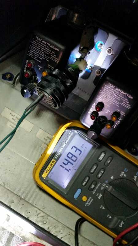
We shot both directions. The hard loop connections and up, read 1.8K (all three turbine elements), the harness side read open. We then went down to the gearbox "aft" loop connection and disconnected one wire also. The loop itself read 6.8K. The harness was open on one of the wires.


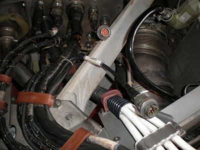
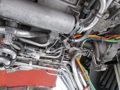
This is all a little tricky because the actual aircraft layout dos not match the schematic. From the pylon plug down you hit TB3. (Engine right at 3 o'clock)


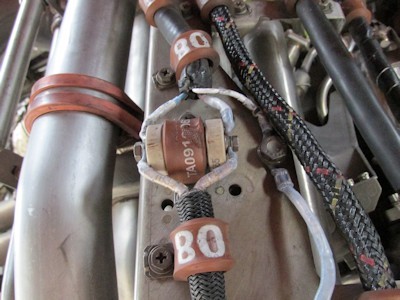
That harness then splits. One segment to the gearbox, one to the lower turbine. In actuality, two sets of wires go to the gearbox and then one set back-tracks up the harness, through the "Y" and then on to the lower turbine element.


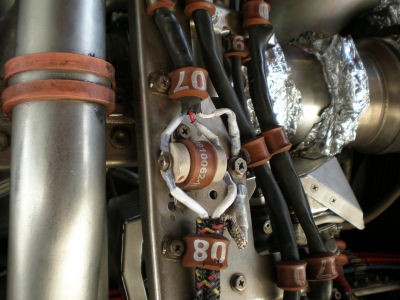
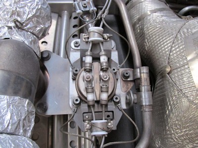
On the upper connector of the lower turbine, the next two elements split off and go upward. The schematic depicts a harness between each loop, but only one harness is used. The loops are still all in parallel, but it can be confusing when trying to compare the engine to the print.
The 6.8K that we read from the E/E was "just" the gearbox loop. With the harness open to the lower turbine. It and the two loops above were not in the circuit. As stated above, when the other three elements were shot, they read 1.8K as a group. The aircraft had a significant history of "B" loop problems. I shook and tapped the remaining sections. Nothing jumped out and grabbed me as being screwed up.

This problem almost exactly mirrored the one above. Both had a open harness segment leg.....
Last edit: 9 years 5 months ago by Mark.

Please Log in or Create an account to join the conversation.

More
8 years 5 months ago #142 by Mark
Just for reference: These are the readings I got at the engine to pylon disconnect reading the complete loop system on the engine itself.
The second pic is the reading from the FDCU to the engine.
As a note, both "A" and "B" loop readings were within an ohm of each other at both of these locations.


Attachments:

Please Log in or Create an account to join the conversation.

Time to create page: 0.622 seconds